Draw A Circuit Diagram For The Circuit Of Figure 1
Draw A Circuit Diagram For The Circuit Of Figure 1 - We usually ignore any resistance from the wires. Browse circuits made by other users of circuit diagram. Smartdraw's intelligent lines will make sure your symbols attach correctly and stay attached to your components even when you move them around. First, we need to identify the components in the circuit. Draw a circuit diagram for the circuit of (figure 1). Web here, we note the equivalent resistance as req. Web upload and share your circuit designs. Now, let's draw the circuit diagram using standard symbols for each component: Web you'll get a detailed solution from a subject matter expert that helps you learn core concepts. You'll get a detailed solution from a subject matter expert that helps you learn core concepts. Draw a circuit diagram for the circuit of (figure 1). Web a simple circuit diagram with component symbols. This is a circuit that travels over every edge once and only once and starts and ends in the same place. First, we need to identify the components in the circuit. Smartdraw's intelligent lines will make sure your symbols attach correctly and. A student builds the circuit below. Smartdraw's intelligent lines will make sure your symbols attach correctly and stay attached to your components even when you move them around. (a) the original circuit of four resistors. The two truth tables should be identical. These diagrams are maps that anyone can read to see how to build the circuit. The resistors r3 and r4 are in series and the equivalent resistance is r34 = 10ω (c) step 2: Generating schematic diagrams from boolean expressions Design circuits online in your browser or using the desktop application. Battery potential view the full answer step 2 final answer previous question next question transcribed image text: We usually ignore any resistance from the. 10μf 12 v 50 ω 100 50 0 10μf 12 v 100 ww 50 12 v figure 1 of 1 100 ω 10μf 100 100 + 50 12 v 12 v 50 10 μf 10μf ww www + +. We usually ignore any resistance from the wires. (ii) a car parked on a side road. First, we need to identify. You'll get a detailed solution from a subject matter expert that helps you learn core concepts. (ii) a car parked on a side road. We usually ignore any resistance from the wires. What is the resistance of r ? Which one of them is moving faster? Thus far, this unit of the physics classroom tutorial has focused on the key ingredients of an electric circuit and upon the concepts of electric potential difference, current and. Web calculations from circuit diagrams. Circuit diagram is a free application for making electronic circuit diagrams and exporting them as images. Circuit symbols and circuit diagrams. The inductive reactance of the. Web draw your circuit diagram the easy choice for creating your circuit drawing online easy to use start with a circuit diagram template and easily add components from a library of circuit drawing symbols. This problem has been solved! Draw a circuit diagram for the circuit of (figure 1). Web circuit symbols and circuit diagrams. There are other euler circuits. Circuit symbols and circuit diagrams. Web thus, the switch is in off position and the circuit is not closed. 1 of 1a circuit is shown in the figure. Identify the components in the circuit: Web circuit diagram circuit diagram in this article, we will explore circuit diagrams in a comprehensive way, understanding their purpose and what they consist of. So, the circuit diagram depicting the image is shown below. (a) the original circuit of four resistors. 10μf 12 v 50 ω 100 50 0 10μf 12 v 100 ww 50 12 v figure 1 of 1 100 ω 10μf 100 100 + 50 12 v 12 v 50 10 μf 10μf ww www + +. Draw a circuit diagram. Inputs a and b lead into an and gate with output x. What is the resistance of r ? Examples of circuit diagrams that showcase different circuit configurations and the symbols used in them are explained. You'll get a detailed solution from a subject matter expert that helps you learn core concepts. Web thus, the switch is in off position. Draw a circuit diagram for the circuit of (figure 1). Learn for free about math, art, computer programming, economics, physics, chemistry, biology, medicine, finance, history, and more. The free end of battery should be connected to the safety pin. Item 9 draw a circuit diagram for the circuit of (figure 1). You'll get a detailed solution from a subject matter expert that helps you learn core concepts. First, we need to identify the components in the circuit. (i) a car moving with a constant speed. The inductive reactance of the circuit. There are other euler circuits for this graph. (ii) a car parked on a side road. Calculate the following parameters for the allocated values (assuming the capacitor is ideal and r1 is represents the resistance of the inductor): Web a simple circuit diagram with component symbols. You'll get a detailed solution from a subject matter expert that helps you learn core concepts. In figure p23.1, we have a battery (or voltage source), a resistor, and a capacitor connected in series. Battery potential view the full answer step 2 final answer previous question next question transcribed image text: Web engineering electrical engineering electrical engineering questions and answers figure 1 table 1 4) draw the timing diagram for the circuit shown in figure 1 with the delay of each gate as provided in table 1.
How To Write A Circuit Diagram

How To Draw Electrical Circuit Diagram

How To Draw A Basic Circuit Diagram Circuit Diagram

Draw Schematic Diagram Of A Circuit

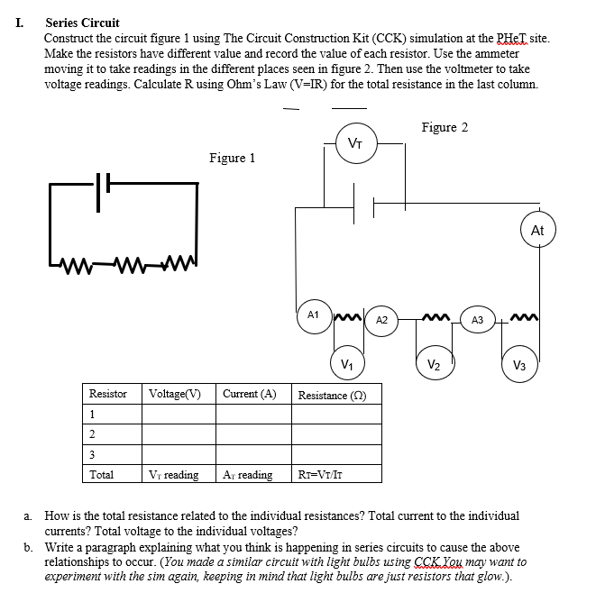
Solved I. Series Circuit Construct the circuit figure 1

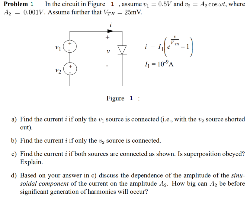
Solved Problem 1 In the circuit in Figure 1 , assume v1 =
28 Draw A Circuit Diagram For The Circuit Of (figure 1) . Wiring

3 Rules For Drawing Circuit Diagrams

Draw a circuit diagram for the circuit of (figure 1). AnswerData

How To Draw Circuit Diagrams On Computer
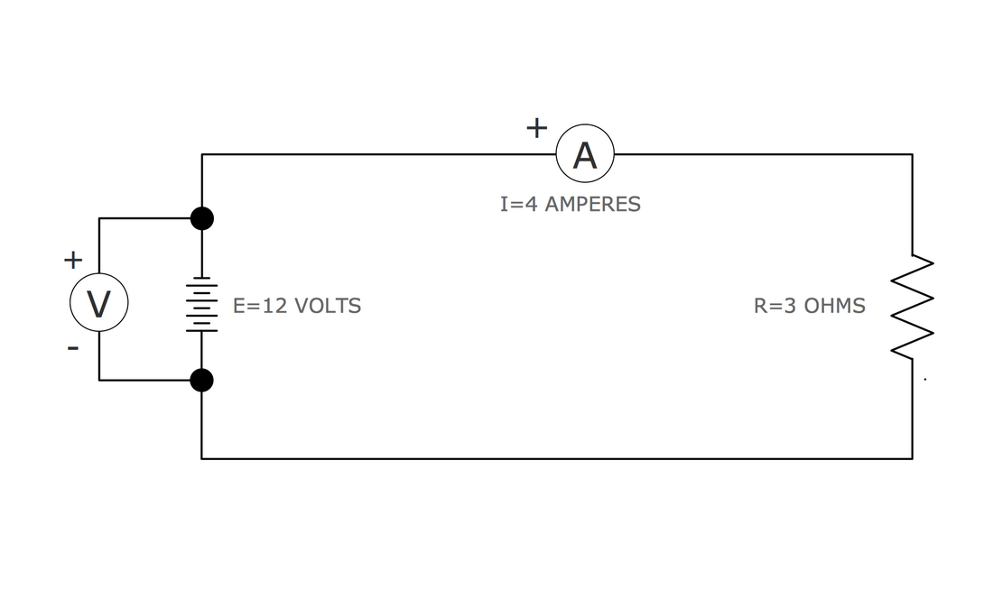
Web A Simple Circuit Contains The Minimum Amount Of Components That Allow It To Be A Functional Electric Circuit:
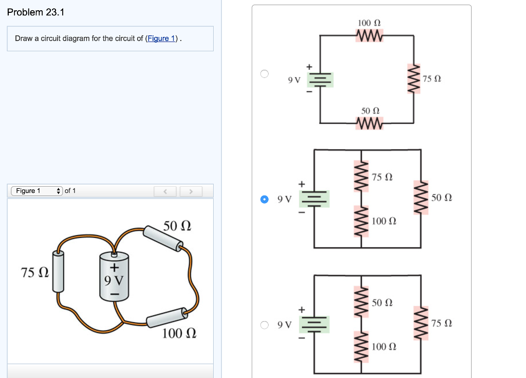
Draw A Circuit Diagram For The Circuit Of (Figure 1).
So, The Circuit Diagram Depicting The Image Is Shown Below.
This Problem Has Been Solved!
Related Post:
