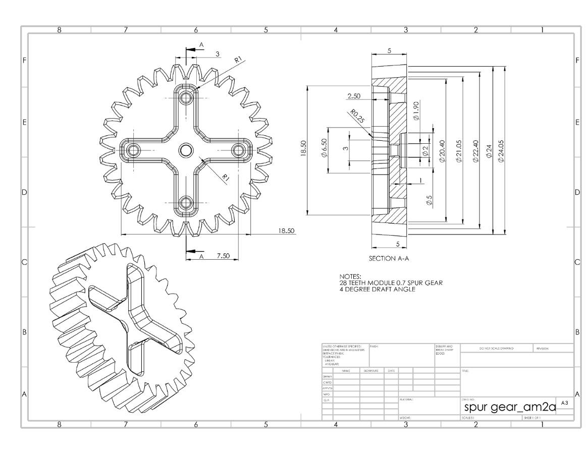
Drawing Of Spur Gear
Drawing Of Spur Gear - A spur gear calculator uses parameters including the tooth count, gear module, and pressure angle to generate the key dimensions of an external spur gear. It will show the boundary creation dialogue. The program then generates the gear profile for you. Web engineering drawings for spur and helical gears $ 220.00 the thors course, engineering drawings for spur and helical gears, teaches the fundamental concepts needed to read and interpret a gear drawing. Web in this vedio focused on draw base circle by given pressure angle and by using mini drafter. Calculate and draw the pitch circle. Web 2 detail drawings (individual gears) 2.1 contours and edges represent the contours and the edges of each gear (see figures 1,2 and 3), as if they were,. Follow along using the transcript. The diameter of the pitch circle is calculated below; Web gear designs can be modeled using a gear maker, also known as a gear generator, a simple free online tool used for creating spur gears. To design successful spur gear systems, we must adopt an engineering approach. Create equidistant points around the circle to represent the teeth’s positions. Follow along using the transcript. Using this example you will be able to draw a spur gear having any number of teeth and pitch. Next, you specify the number of teeth, module, and pressure angle. Let’s see the processes to examine the shape of the gears from these basic. Even in the case of a gear that does not have spur teeth or that has an odd number of teeth. It will show the boundary creation dialogue. But let's try something new. This tutorial gives a different approach on drawing a spur gear. Web the spur gear is a cylindrically shaped tooth component that is used in industrial plants to transmit mechanical movements and to control speed, power, and torque. What is a spur gear? In this comprehensive guide, we will walk you through the process. Follow along using the transcript. • if teeth are too large, the gear designer must: Web gear designs can be modeled using a gear maker, also known as a gear generator, a simple free online tool used for creating spur gears. Web drawing a spur gear in millimeters involves a series of technical steps which require precision and an understanding of gear mechanics. Web this calculator generates the.dxf and.svg files for making external spur gears,. Dxf files are accepted by most machines that cut 2d shapes such as cnc wood routers, laser cutters, waterjets, and cnc plasma tables. But let's try something new. Smaller teeth are weaker increase pitch circle radius. Web in this vedio focused on draw base circle by given pressure angle and by using mini drafter. Bigger, faster, noisier gears increase pressure. Web how to draw a spur gear manually and more understanding the art of manual spur gear drawing. In this comprehensive guide, we will walk you through the process. We can also use pedit command. Web in this tutorial video i will sketch spur gear in solidworks with the help of toolbox.please subscribe our channel for more videos and projects. What is a spur gear? Common applications of spur gears. Draw a circle that will represent the gear’s pitch circle. But let's try something new. A spur gear calculator uses parameters including the tooth count, gear module, and pressure angle to generate the key dimensions of an external spur gear. A spur gear calculator uses parameters including the tooth count, gear module, and pressure angle to generate the key dimensions of an external spur gear. Common applications of spur gears. Web in this example we will draw the 36 tooth, 24 pitch spur gear. Web this calculator generates the.dxf and.svg files for making external spur gears, rack and pinion sets,. Web in this tutorial video i will sketch spur gear in solidworks with the help of toolbox.please subscribe our channel for more videos and projects in solidworks. Web this free, highly functional gear drawing software allows you to easily create gear drawings by entering various parameters, hub shapes, hole dimensions, keyway dimensions, and other information. Web engineering drawings for spur. It will show the boundary creation dialogue. Draw lines from the center of the circle to these points to function as the teeth’s base. Web make the profile of the gear tooth spaces. Trim the circles side ways. Next, you specify the number of teeth, module, and pressure angle. Even in the case of a gear that does not have spur teeth or that has an odd number of teeth. Begin by laying out the pitch, root and outside circles of the 36 tooth gear. By following the instructions in this article, you can design these systems according to your system’s parameters. Web in this vedio focused on draw base circle by given pressure angle and by using mini drafter. Drawing a spur gear manually might seem like a daunting task,. To design successful spur gear systems, we must adopt an engineering approach. This tutorial gives a different approach on drawing a spur gear. Choosing the right spur gears. Click inside the region and then press. This command is going to be used for creating the polyline. Let’s see the processes to examine the shape of the gears from these basic. Web drawing a spur gear in millimeters involves a series of technical steps which require precision and an understanding of gear mechanics. In this comprehensive guide, we will walk you through the process. Web spur gear systems are one of the most used engineering systems in the machine elements world. Next, you specify the number of teeth, module, and pressure angle. 2.2 pitch surface draw the pitch surface with a thin, long chain line, even in concealed portions.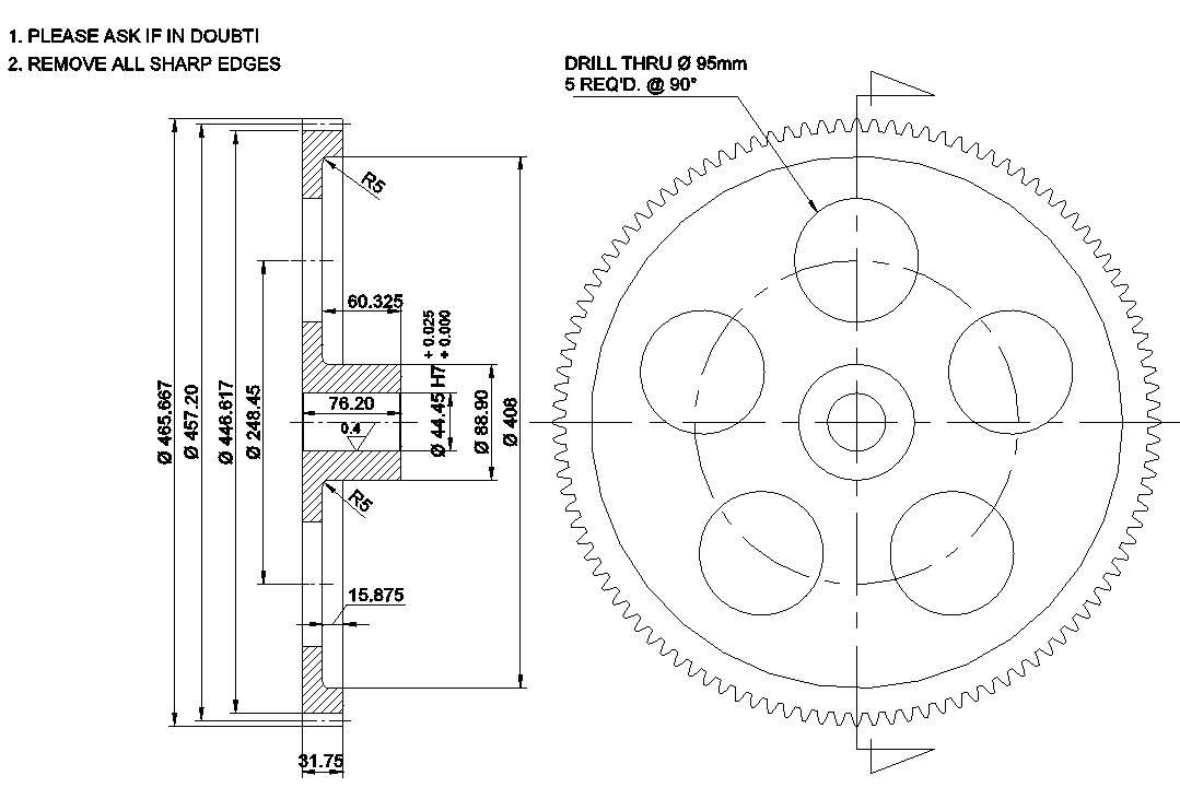
spur gear drawing autocad download howdoesdigitalartwork
Spur Gear Drawing at GetDrawings Free download
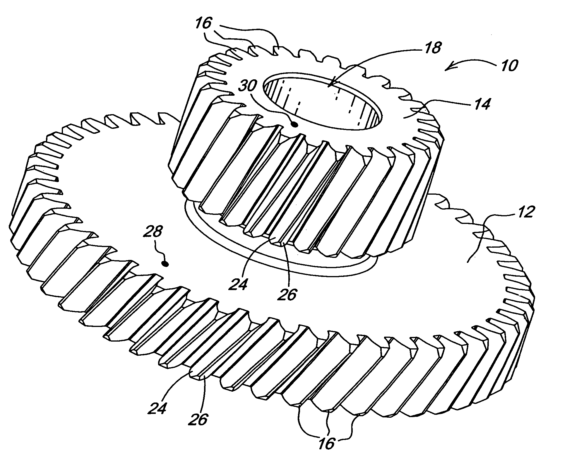
Spur Gear Drawing at GetDrawings Free download
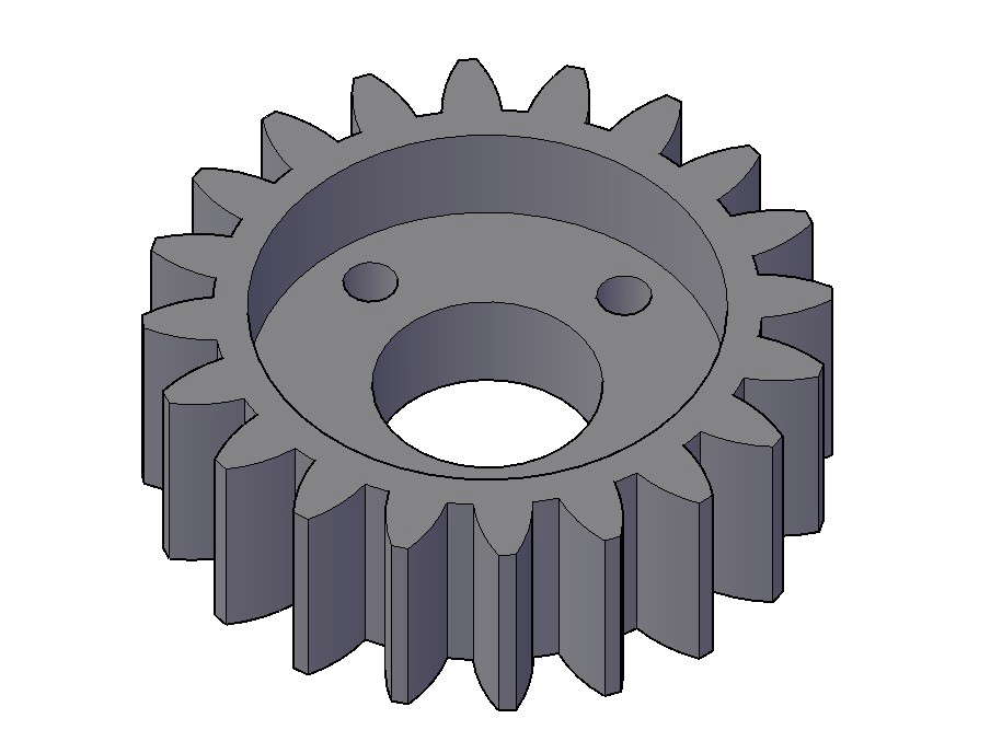
Isometric view of the Spur Gear 20T M2.25 Section and Elevation
Spur Gears Geometry of spur gears and gear meshes
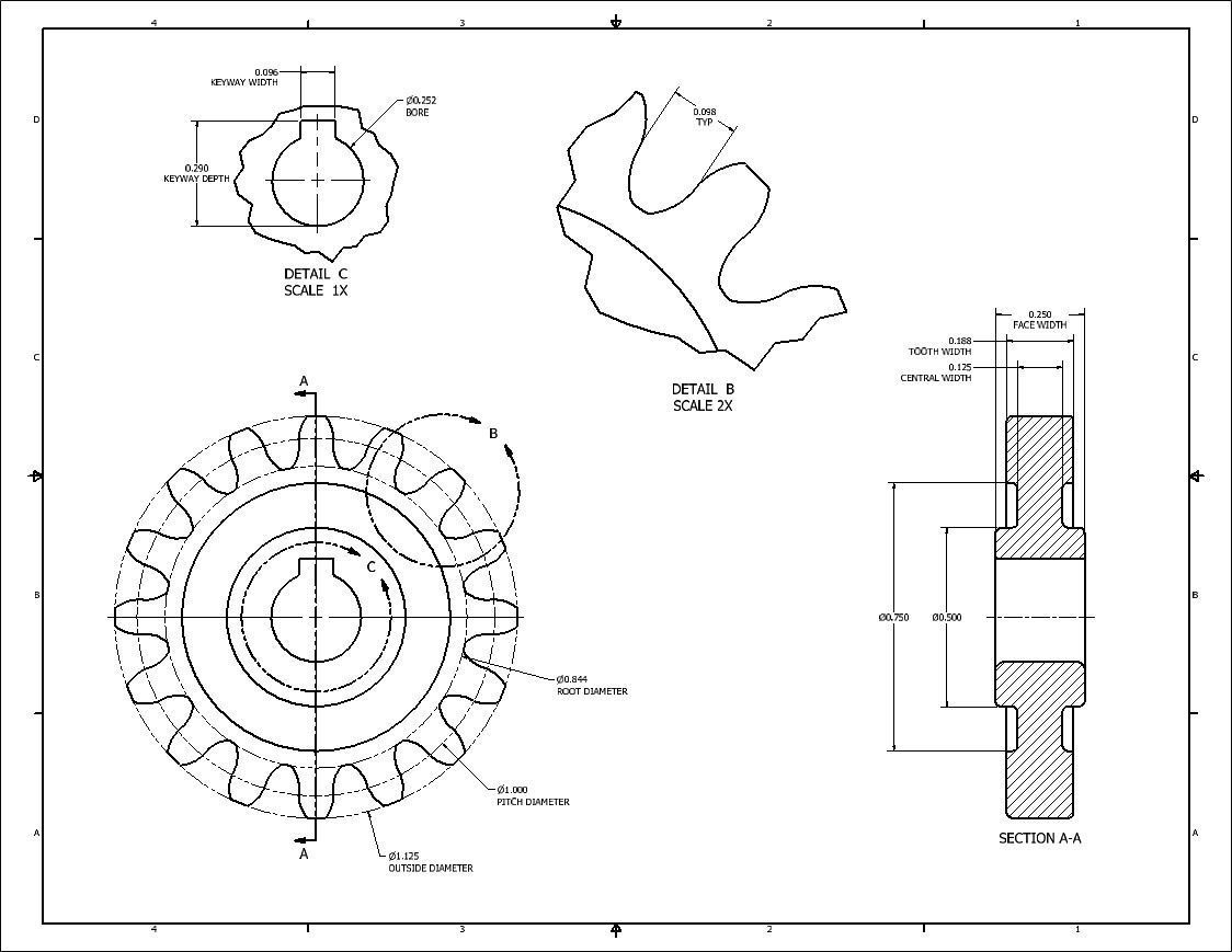
Spur Gear Drawing at GetDrawings Free download
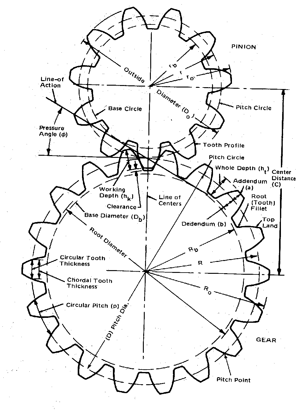
Spur Gear Drawing at GetDrawings Free download

Spur Gear Drawing at Explore collection of Spur
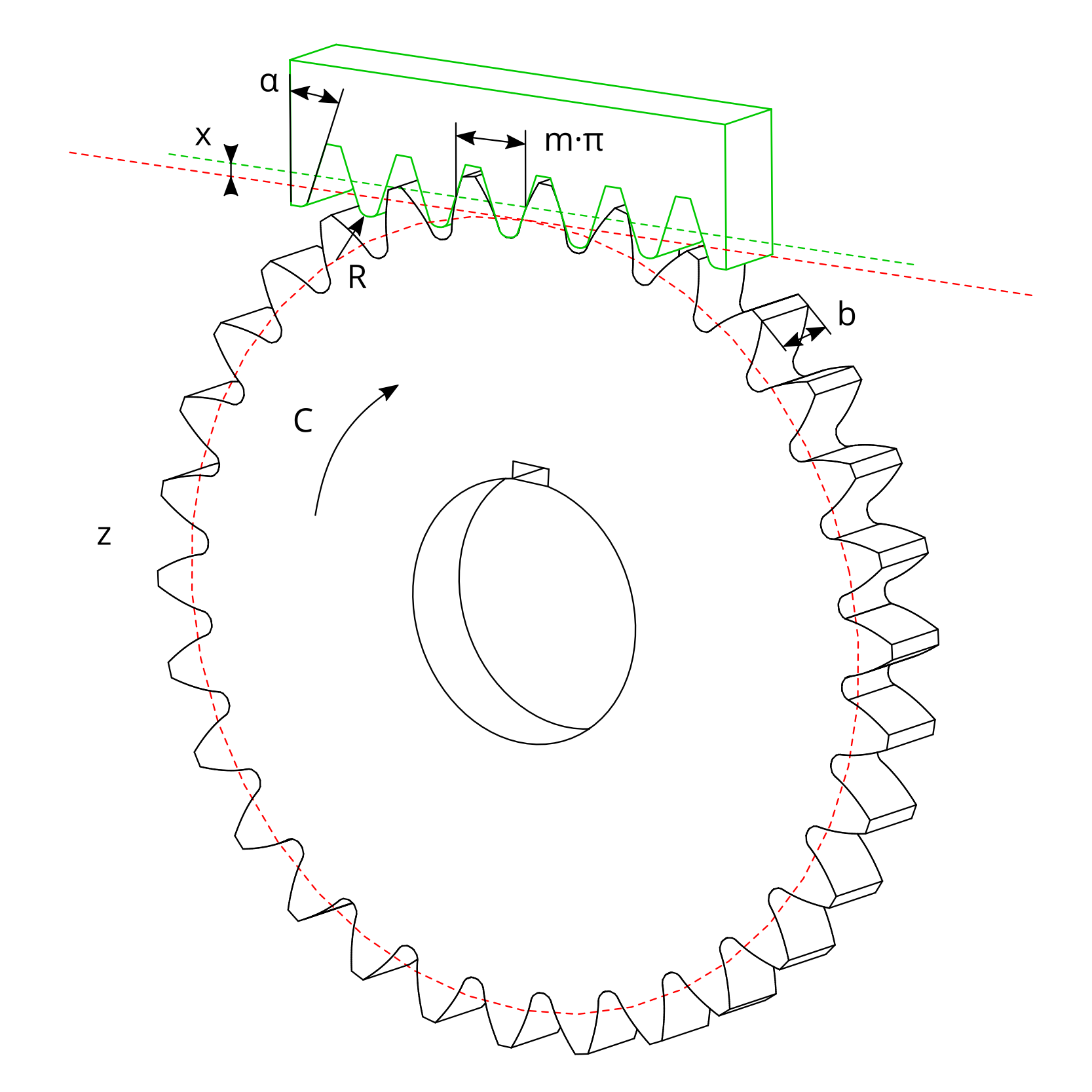
Spur Gear Sketch at Explore collection of Spur
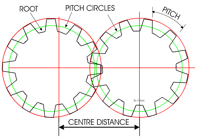
Spur Gear Drawing at GetDrawings Free download
A Spur Gear Calculator Uses Parameters Including The Tooth Count, Gear Module, And Pressure Angle To Generate The Key Dimensions Of An External Spur Gear.
Web 2 Detail Drawings (Individual Gears) 2.1 Contours And Edges Represent The Contours And The Edges Of Each Gear (See Figures 1,2 And 3), As If They Were,.
2.5 Representative Or Member Of A Corporation, Educational Institution, Or Trade Organization?
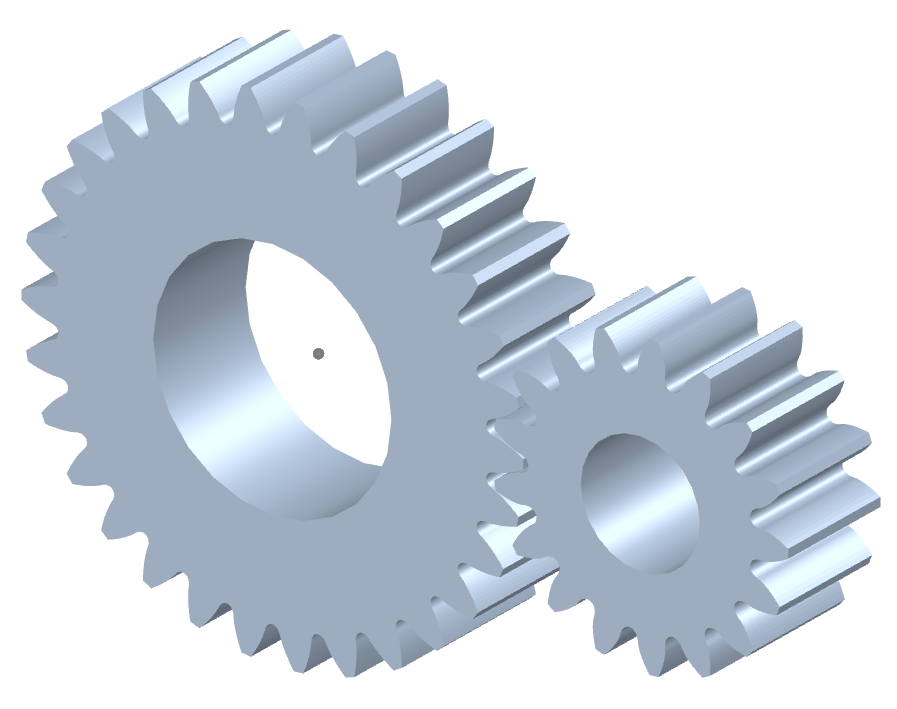
Web The Spur Gear Is A Cylindrically Shaped Tooth Component That Is Used In Industrial Plants To Transmit Mechanical Movements And To Control Speed, Power, And Torque.
Related Post:
