Electrical Architectural Drawing Symbols
Electrical Architectural Drawing Symbols - These are the ones we have on our shelf. Web electrical plan symbols are universally recognized icons or drawings used to depict the various components of an electrical system. Web below are some of the most common electrical symbols used in architectural blueprints: Web this handy guide includes everything from property lines and electrical symbols to elevation markers and scale bars. Web this article delves into the world of electrical diagram symbols, explains their meanings and highlights their importance in the fabric of architectural design. Draw lines between lights and the switches that control them, and between receptacles that are on the same circuits. Swinging doors sliding doors windows shower recesses, etc. Web use symbols — “s” for switches, and circles for can lights — to represent the devices. Electrical plan symbols used in electrical drawings, including power, lighting, security, fire alarm, and communications symbols. 6 common types of floor plan symbols Duplexes and outlets standard outlets: Web understand the symbols used in the schematic. Electrical components are also represented on floor plans using australian standard symbols. Introducing the winners of architizer's inaugural vision awards. In this publication, the term “electrical” is used to include electrical, electronic, and communications systems covered by the national electrical code (nfpa 70). Web architectural drawings (floor plans) use symbols to represent features of a building such as: 6 common types of floor plan symbols Duplexes and outlets standard outlets: Symbols for the drawings (other than those used previously in this text) are shown and. Learn everything you need to know about reading blueprints in mt copeland’s online class, taught by professional builder. Electrical components are also represented on floor plans using australian standard symbols. Web in every electrical diagram, we represent electrical equipment with the help of electric symbols. Abbreviations and numbers next to the duplex provide additional information. Draw lines between lights and the switches that control them, and between receptacles that are on the same circuits. Web this article delves. They are not very complicated items but shockingly i have some. The mechanics of a building are represented by service symbols, which help identify elements such as mechanical ventilation, soil pipes, and incoming. In this publication, the term “electrical” is used to include electrical, electronic, and communications systems covered by the national electrical code (nfpa 70). We give them a. Web understand the symbols used in the schematic. These electrical symbols are used to simplify the drafting and to understand the drawing. Learn the different symbols for capacitors, resistors, switches, relays, inductors, batteries and. Web the electrical drawings consist of electrical outlets, fixtures, switches, lighting, fans, and appliances. Web below are some of the most common electrical symbols used in. Web understand the symbols used in the schematic. Mep (mechanical, electrical, and plumbing) a. Duplexes a circle off of the wall and connected to it by two parallel lines represents a typical outlet (or receptacle) with two sockets. Symbols for the drawings (other than those used previously in this text) are shown and. Plan, elevation, and section symbols; Duplexes and outlets standard outlets: Abbreviations and numbers next to the duplex provide additional information. These are the ones we have on our shelf. Therefore, it is necessary to use the door symbol to. This publication also summarizes recommended drawing practices for electrical construction drawings. Draw lines between lights and the switches that control them, and between receptacles that are on the same circuits. General notes, abbreviations, legends, and symbols, are found on the first page of the electrical drawings. Introducing the winners of architizer's inaugural vision awards. These electrical symbols are used to simplify the drafting and to understand the drawing. The most commonly. These symbols are commonly used in architectural plans such as reflective ceiling plans to denote specific electrical devices, circuits, and connections. In this publication, the term “electrical” is used to include electrical, electronic, and communications systems covered by the national electrical code (nfpa 70). Web understand the symbols used in the schematic. Door symbols in architecture drawing 99% of built. These electrical symbols are used to simplify the drafting and to understand the drawing. They are not very complicated items but shockingly i have some. Most electrical drawings will use standard symbols for components. Different types of doors exist in a structure, so the architect will use door symbols to indicate which door types will be in certain areas. The. Electrical plan symbols used in electrical drawings, including power, lighting, security, fire alarm, and communications symbols. Web below are some of the most common electrical symbols used in architectural blueprints: May 24, 2021 by bob borson 2 comments. Door symbols in architectural drawings show readers where the doors in the building will be. An integral part of any set of drawings for the construction of a building is the wiring plan or layout. These symbols are commonly used in architectural plans such as reflective ceiling plans to denote specific electrical devices, circuits, and connections. Typically represented by a circle connected by two parallel lines to a. Web the electrical drawings consist of electrical outlets, fixtures, switches, lighting, fans, and appliances. These electrical symbols are used to simplify the drafting and to understand the drawing. Web this handy guide includes everything from property lines and electrical symbols to elevation markers and scale bars. Architizer editors details feast your eyes on the most outstanding architectural photographs, videos, visualizations, drawing and models of 2023: Web typical electrical drawing symbols and conventions. They are not very complicated items but shockingly i have some. Web architectural drawings (floor plans) use symbols to represent features of a building such as: Draw lines between lights and the switches that control them, and between receptacles that are on the same circuits. Introducing the winners of architizer's inaugural vision awards.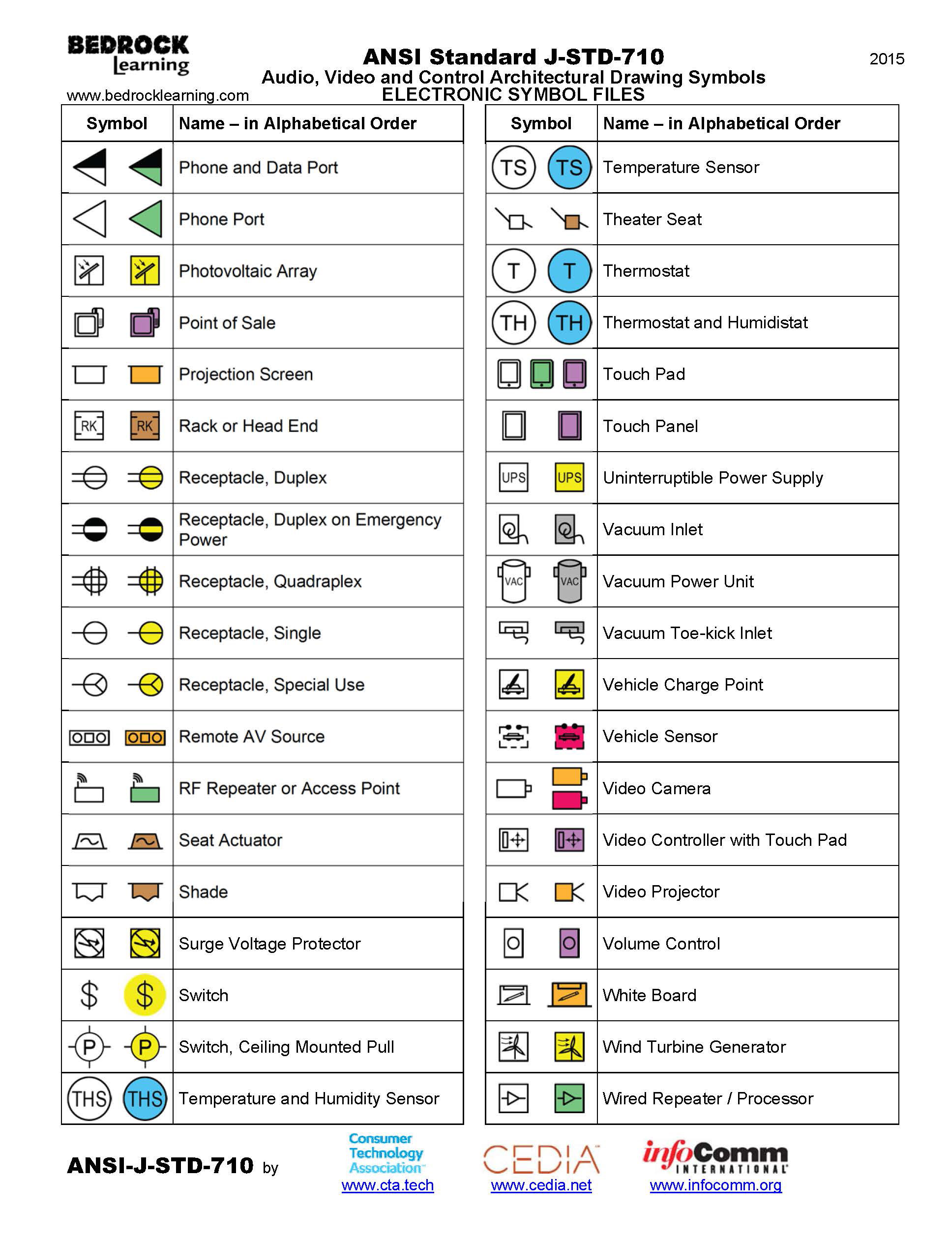
ANSI Standard JSTD710 Architectural Drawing Symbols Bedrock Learning

Building Electrical Symbols Floor Plan Symbols Chart Pdf Wikizie Co
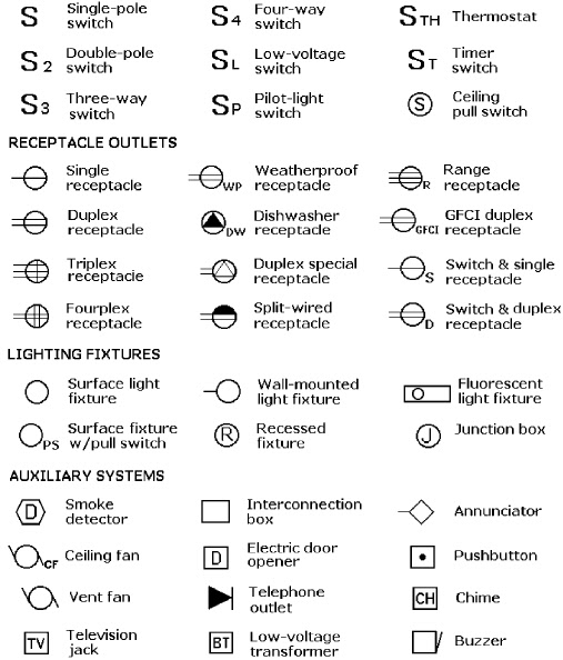
ELECTRICAL WIRING DIAGRAM GRAPHIC SYMBOLS BASIC INFORMATION AND
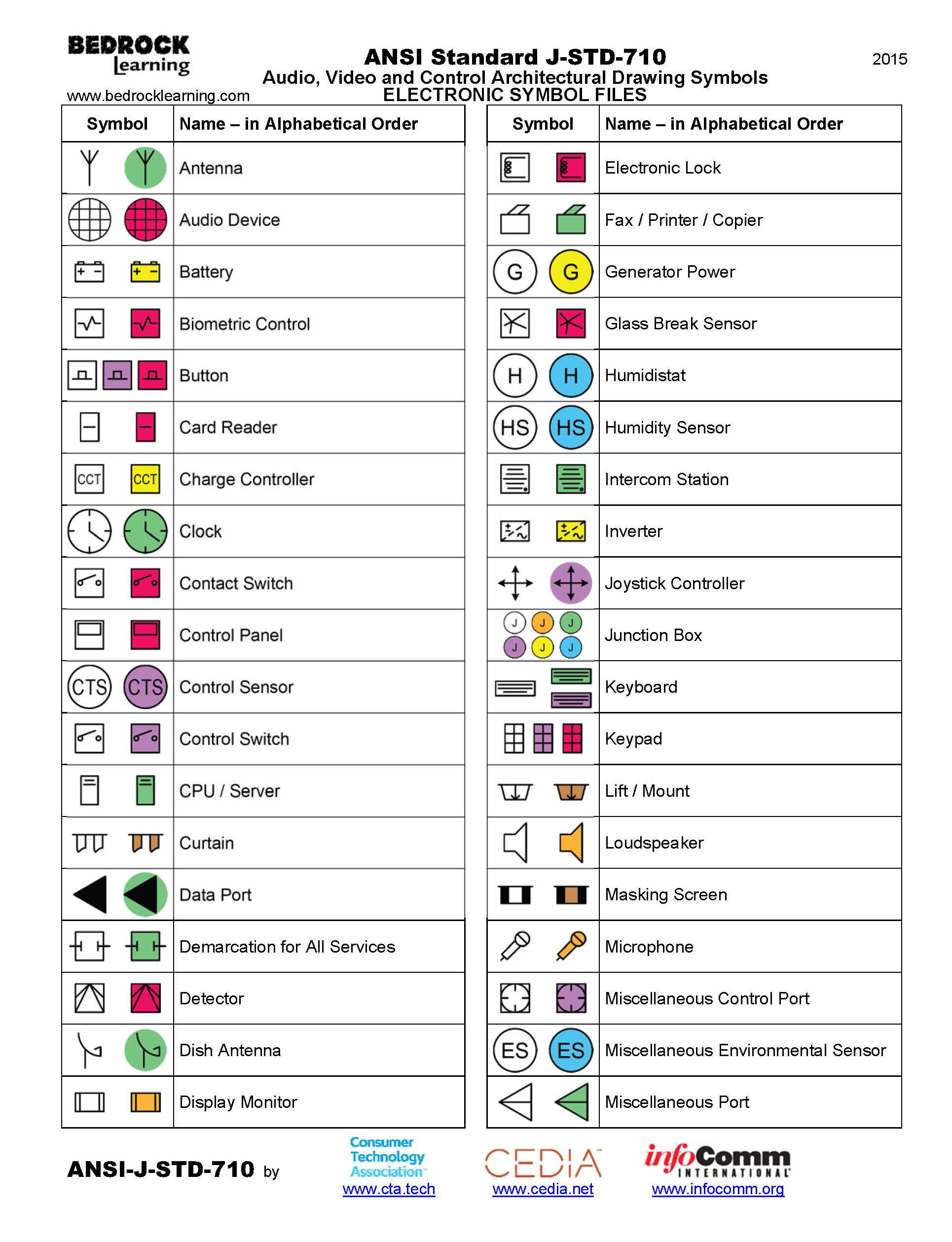
ANSI Standard JSTD710 Architectural Drawing Symbols Bedrock Learning

Free CAD Blocks Electrical Symbols
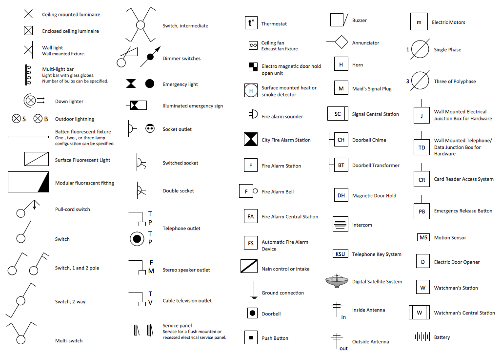
electrical house wiring symbols pdf Wiring Diagram and Schematics

electrical outlet symbol Floor plan symbols, Electrical symbols

Free Electrical Blueprint Symbols ((TOP))
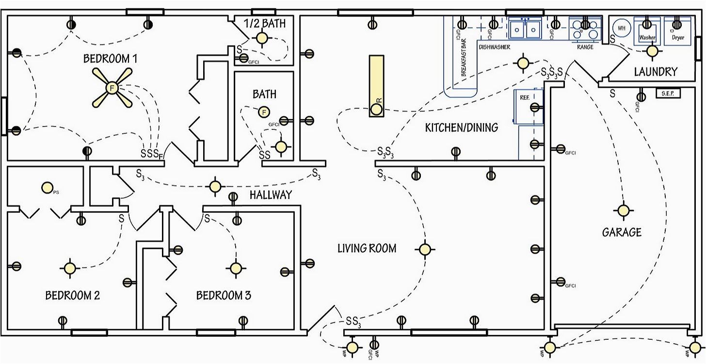
Electrical Symbols for House Plans
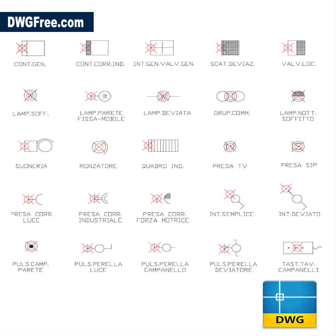
Electrical symbols residential Drawing. Download free in Autocad.
Web This Article Delves Into The World Of Electrical Diagram Symbols, Explains Their Meanings And Highlights Their Importance In The Fabric Of Architectural Design.
Different Types Of Doors Exist In A Structure, So The Architect Will Use Door Symbols To Indicate Which Door Types Will Be In Certain Areas.
Electrical Components Are Also Represented On Floor Plans Using Australian Standard Symbols.
The Mechanics Of A Building Are Represented By Service Symbols, Which Help Identify Elements Such As Mechanical Ventilation, Soil Pipes, And Incoming.
Related Post: