Hvac Schematic Drawings
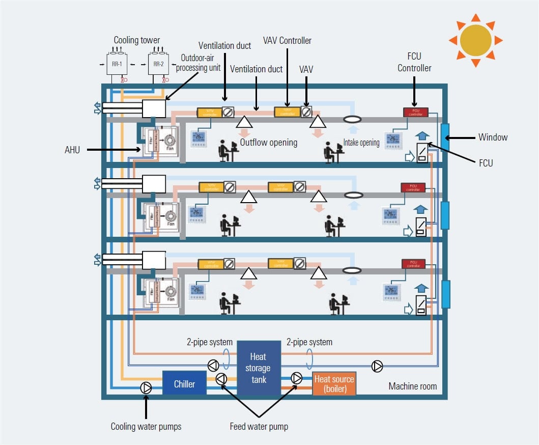
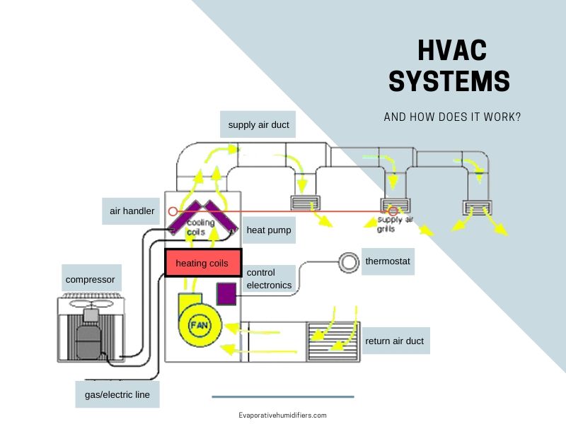
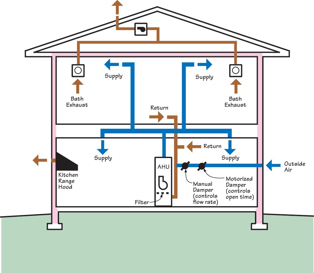
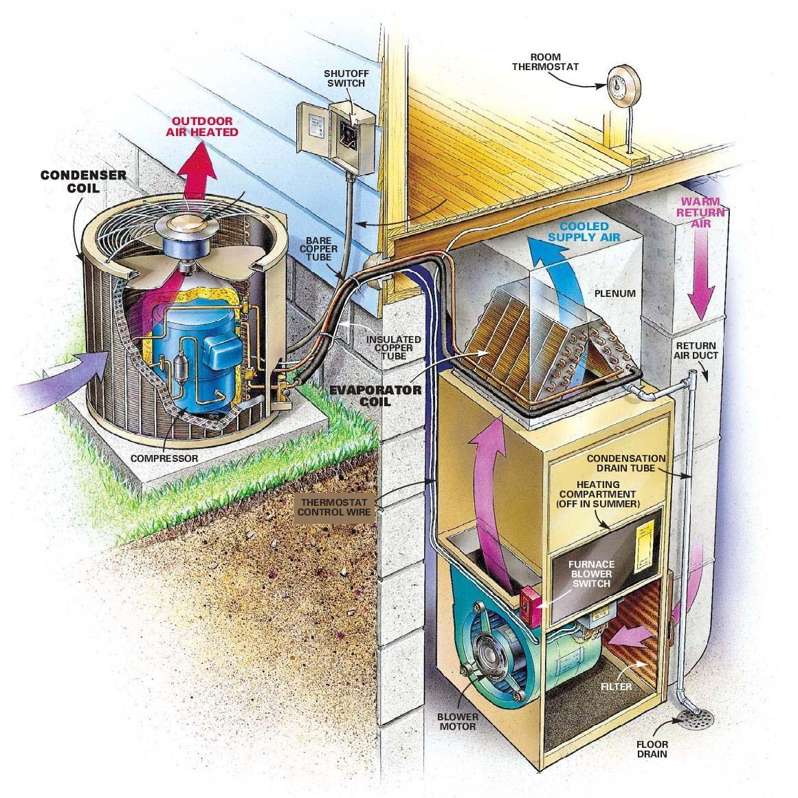
Hvac Schematic Drawings - Web what you should know about your hvac's schematic diagrams gain insights into central air conditioning systems through schematic diagrams. We walk through some of the basics and most common symbols associated with reading air conditioner wiring diagrams. Ac duct design calculation service. 1) geographical site conditions (latitude, longitude, wind velocity, precipitation etc.) 2) outdoor design conditions (temperature, humidity etc) 3) indoor design conditions 4) building characteristics (materials, size, and shape) Web hvac basics air handling system components/layout: Web basis & preliminary architectural drawings. We use various hvac symbols to design schematic wiring and circuit diagrams to depict the layout and working mechanism of hvac systems. Web in hvac (heating, ventilation, and air conditioning) systems, electrical diagrams are used to represent the various components and electrical connections within the system. They’re the language of thermostat diagrams, heating, ventilation, and air conditioning equipment systems, including new ductwork. Get to know about their significance for hvac maintenance and. Web in hvac (heating, ventilation, and air conditioning) systems, electrical diagrams are used to represent the various components and electrical connections within the system. Web the hvac drawings provide details for the ac system, refrigerant pipe connections, chiller, and duct layouts. How to go from a 3 wire to a 4 wire configuration. Ladder, line, and installation diagrams. Here’s how. They also help to control humidity levels and remove dust, allergens, and other airborne particles. The design basis typically includes information on: Web in hvac (heating, ventilation, and air conditioning) systems, electrical diagrams are used to represent the various components and electrical connections within the system. Create diagrams of heating and air conditioning systems, air flows, electrical systems, ducts, and. Web a qualified hvac contractor will be able to figure this out for you more accurately, but here is a helpful chart so you can know what to expect: Create diagrams of heating and air conditioning systems, air flows, electrical systems, ducts, and piping for both home and commercial properties. Web this video provides an overview of how to read. 1) geographical site conditions (latitude, longitude, wind velocity, precipitation etc.) 2) outdoor design conditions (temperature, humidity etc) 3) indoor design conditions 4) building characteristics (materials, size, and shape) Common hvac industry terms like absolute humidity, pressure, temperature and more. Indoor temperature and humidity loads This is what keeps you cool when the summer heat hits. The hvac plans include plan. Web a qualified hvac contractor will be able to figure this out for you more accurately, but here is a helpful chart so you can know what to expect: These symbols provide a standardized way of communicating information about the system’s design and operation. Ladder, line, and installation diagrams. Web in hvac (heating, ventilation, and air conditioning) systems, electrical diagrams. These symbols provide a standardized way of communicating information about the system’s design and operation. It contains information about the drawing type, the legend, the project title, related companies and more. Our manual d service, is a complete custom ac duct design for any residential project. This is what keeps you cool when the summer heat hits. These diagrams are. The hvac plans include plan notes to describe the installation details and fixture types. Web in hvac (heating, ventilation, and air conditioning) systems, electrical diagrams are used to represent the various components and electrical connections within the system. Air enters the system from the outside through an air duct and is mixed just before the filters with return air from. Web basis & preliminary architectural drawings. Each symbol represents a specific component, such as a motor, valve, or temperature sensor, and is. Web the hvac equipment is shown on the mechanical equipment schedule drawings. They’re the language of thermostat diagrams, heating, ventilation, and air conditioning equipment systems, including new ductwork. We use various hvac symbols to design schematic wiring and. Web ventilation systems remove stale indoor air, replacing it with fresh air from outside. Web the types of hvac symbols. Web the hvac equipment is shown on the mechanical equipment schedule drawings. Web basis & preliminary architectural drawings. These diagrams are essential for understanding the electrical circuitry and troubleshooting any issues that may arise. Air enters the system from the outside through an air duct and is mixed just before the filters with return air from the space. The hvac plans include plan notes to describe the installation details and fixture types. Whenever you approach a wiring diagram, look at the whole thing, especially the legend and notes. It contains information about the drawing. These symbols provide a standardized way of communicating information about the system’s design and operation. Get to know about their significance for hvac maintenance and. Web title block title block is the standard cover for hvac drawings. Web a qualified hvac contractor will be able to figure this out for you more accurately, but here is a helpful chart so you can know what to expect: Notes and legend this section of the drawing consists of notes such as disclaimers, things to highlight and how to read the drawing. Each symbol represents a specific component, such as a motor, valve, or temperature sensor, and is. Web hvac schematic drawing. Web the hvac equipment is shown on the mechanical equipment schedule drawings. Ac duct design calculation service. Ladder, line, and installation diagrams. Create diagrams of heating and air conditioning systems, air flows, electrical systems, ducts, and piping for both home and commercial properties. This is what keeps you cool when the summer heat hits. Web in hvac (heating, ventilation, and air conditioning) systems, electrical diagrams are used to represent the various components and electrical connections within the system. Web if you understand an hvac system diagram, you can better understand what’s going wrong when your vents begin to blast warm air. The schematic drawing is the second most important type of hvac drawing. Here you will find the hvac equipment such as air conditioners, air handlers, fan coil units, fans, chillers, cooling towers, pumps, air distribution, expansion tanks, boilers, vfd’s (variable frequency drives), condensers and various other components.
HVAC Systems Renesas
![How Does an HVAC System Work? [Diagram] The Severn Group](https://www.theseverngroup.com/wp-content/uploads/2017/09/SG_HowDoesHVACWork.png)
How Does an HVAC System Work? [Diagram] The Severn Group

Air Conditioning Schematic Diagram

HVAC System How Does it Work, Components and Maintenance Tips

A complete HVAC system includes ducted returns Building America

Residential Master AC and Heat

Hvac System Schematic

HVAC Diagrams Schematic and System 101 Diagrams

Schematic Diagram Of Hvac System

HVAC Diagrams Schematic and System 101 Diagrams
The Design Basis Typically Includes Information On:
Air Enters The System From The Outside Through An Air Duct And Is Mixed Just Before The Filters With Return Air From The Space.
So, Identify The Btu Needed For Each Room And Divide It By 30 To Get The Required Cfm For The Respective Room.
These Diagrams Are Essential For Understanding The Electrical Circuitry And Troubleshooting Any Issues That May Arise.
Related Post: