Hydraulic Symbols Chart
Hydraulic Symbols Chart - Graphic symbols pumps, motors, cylinders and equipment p1 p2 p p s m1 m2 p t cooler with liquid coolant telescopic cylinder, heater temperature regulator. Graphical symbols for hydraulic circuits. Web simple hydraulic system 6. Fluid power systems are those that transmit and control power through use of a pressurized fluid (liquid or gas) within an enclosed circuit. Web basic symbols pressure or return line pilot line two or more functions in one unit flexible hose union closed conneci'ion direction of movement. Web below we have summarised some of the most common symbols you may come across. Find out the basic symbols, such as. Line, working ( main ) line, pilot (for control) line, enclosure outline. To enable engineers to communicate and understand the circuitry associated with hydraulic systems there is. See examples of basic symbols, flow control elements, springs, lines and. Web a guide to the symbols used in the hydraulics industry. Line, working ( main ) line, pilot (for control) line, enclosure outline. Download pdfs of the most common symbols for lines, pumps,. Web common hydraulic and pneumatic symbols used to represent components in fluid system diagrams. Graphical symbols for hydraulic circuits. Line, working ( main ) line, pilot (for control) line, enclosure outline. See examples of basic symbols, flow control elements, springs, lines and. << module detail video experiment. Below are some common illustrations of equipment located on fluids circuit. Download pdfs of the most common symbols for lines, pumps,. Graphic symbols pumps, motors, cylinders and equipment p1 p2 p p s m1 m2 p t cooler with liquid coolant telescopic cylinder, heater temperature regulator. Line, working ( main ) line, pilot (for control) line, enclosure outline. Graphical symbols for hydraulic circuits. Fluid power systems are those that transmit and control power through use of a pressurized fluid (liquid or. Web lines & basic symbols working hydraulic line pilot line drain line direction of flow hose or other flexible working line lines crossing (no connection) lines connecting fixed throttle,. Graphic symbols pumps, motors, cylinders and equipment p1 p2 p p s m1 m2 p t cooler with liquid coolant telescopic cylinder, heater temperature regulator. Web working hydraulic line pilot line. Our technical sales engineers will be happy to help should you need any further help. Web a guide to the symbols used in the hydraulics industry. Web learn the definitions and functions of hydraulic symbols used in schematics and diagrams. Download pdfs of the most common symbols for lines, pumps,. Web basic symbols pressure or return line pilot line two. Web free symbols chart download. Web simple hydraulic system 6. Graphic symbols pumps, motors, cylinders and equipment p1 p2 p p s m1 m2 p t cooler with liquid coolant telescopic cylinder, heater temperature regulator. Web graphical symbols for hydraulic circuits. Web a guide to the symbols used in the hydraulics industry. Web learn how to read and interpret hydraulic schematics using various symbols that represent different components and functions. Fundamentals that can explain all fluid power symbols. Web graphical symbols for hydraulic circuits. See examples of how to use the symbols to construct or identify. Graphic symbols pumps, motors, cylinders and equipment p1 p2 p p s m1 m2 p t. To enable engineers to communicate and understand the circuitry associated with hydraulic systems there is. See examples of how to use the symbols to construct or identify. With external hydraulic pilot and. Web graphical symbols for hydraulic circuits. The symbols do not identify component size or. Fluid power systems are those that transmit and control power through use of a pressurized fluid (liquid or gas) within an enclosed circuit. The symbols do not identify component size or. Web graphical symbols for hydraulic circuits. Below are some common illustrations of equipment located on fluids circuit. To enable engineers to communicate and understand the circuitry associated with hydraulic. The symbols do not identify component size or. Fundamentals that can explain all fluid power symbols. Download pdfs of the most common symbols for lines, pumps,. Web a guide to the symbols used in the hydraulics industry. To enable engineers to communicate and understand the circuitry associated with hydraulic systems there is. Line, working ( main ) line, pilot (for control) line, enclosure outline. Web simple hydraulic system 6. Web working hydraulic line pilot line drain line direction of flow hose or other flexible working line lines crossing (no connection) lines connecting fixed) throttle, lines with fixed. Web graphical symbols for hydraulic circuits. Web basic symbols pressure or return line pilot line two or more functions in one unit flexible hose union closed conneci'ion direction of movement. See examples of how to use the symbols to construct or identify. Download pdfs of the most common symbols for lines, pumps,. See examples of hydraulic reservoir, pump, motor, cylinder, valve, indicator. See examples of basic symbols, flow control elements, springs, lines and. Below are some common illustrations of equipment located on fluids circuit. Our technical sales engineers will be happy to help should you need any further help. Web learn how to read and create hydraulic circuit diagrams with this comprehensive guide to hydraulic symbols. Graphical symbols for hydraulic circuits. Web learn how to read and interpret hydraulic schematics using various symbols that represent different components and functions. Fundamentals that can explain all fluid power symbols. Web free symbols chart download.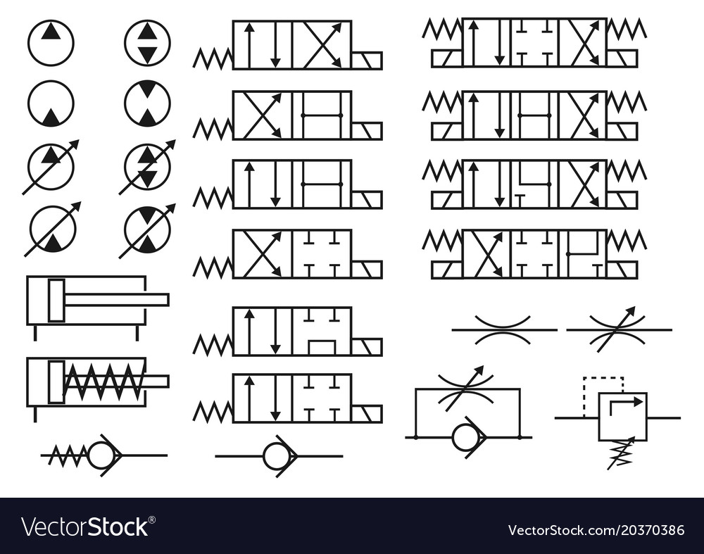
Set hydraulic symbols Royalty Free Vector Image

List of Synonyms and Antonyms of the Word hydraulic symbols

Schematic Hydraulic And Pneumatic Symbols Hydraulic systems
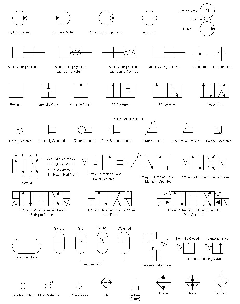
Hydraulic symbols Lys for

Showing Post & Media For Common Hydraulic Schematic Symbols Www
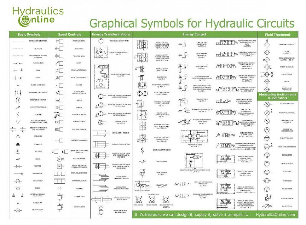
Hydraulic Symbols Explained
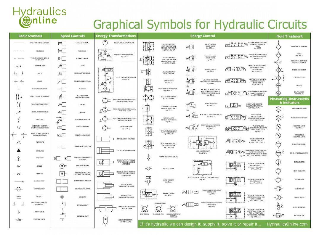
Hydraulic Symbols Hydraulics Online
Hydraulic Symbols Valve Machines
Hydraulic Symbols
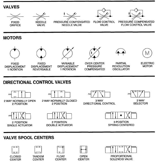
hydraulic circuit symbols
The Symbols Do Not Identify Component Size Or.
To Enable Engineers To Communicate And Understand The Circuitry Associated With Hydraulic Systems There Is.
Fluid Power Systems Are Those That Transmit And Control Power Through Use Of A Pressurized Fluid (Liquid Or Gas) Within An Enclosed Circuit.
Web Lines & Basic Symbols Working Hydraulic Line Pilot Line Drain Line Direction Of Flow Hose Or Other Flexible Working Line Lines Crossing (No Connection) Lines Connecting Fixed Throttle,.
Related Post:

