Hydraulic Valve Symbols Chart
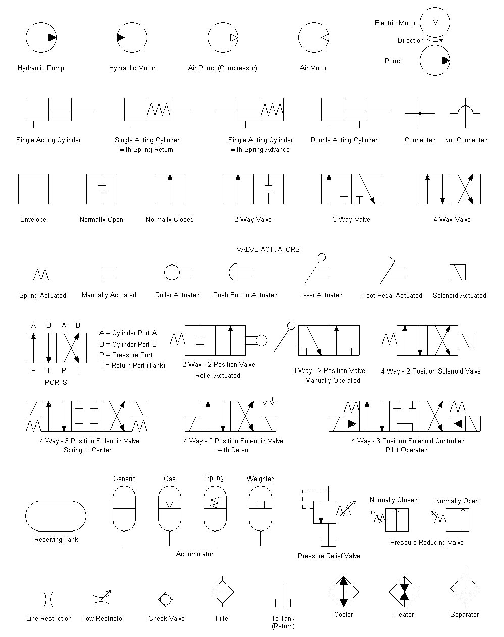
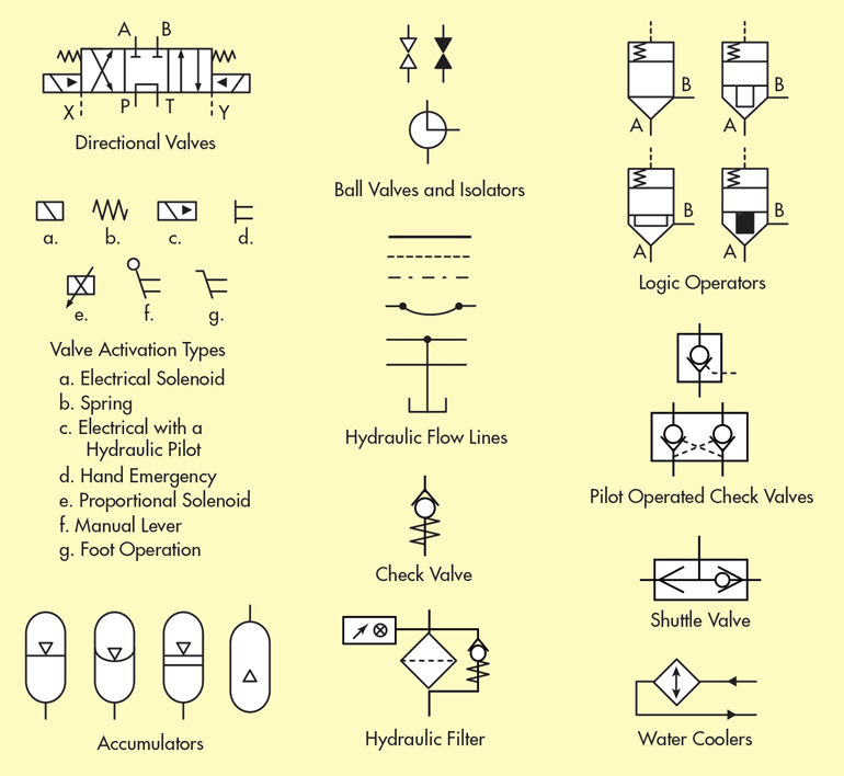
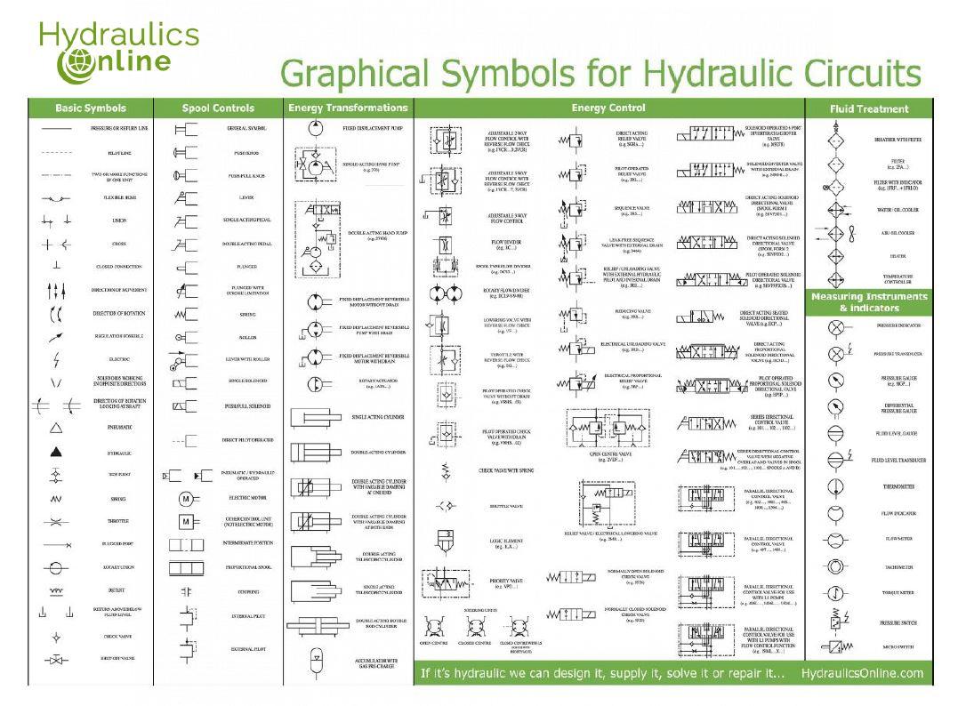
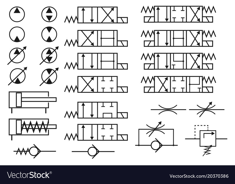
Hydraulic Valve Symbols Chart - Web understanding the hydraulic valve symbols is key to interpreting hydraulic system schematics and effectively troubleshooting any issues that may arise. These symbols provide a visual guide for. Ninety nine percent of hydraulic symbols use one of these three as a foundation. By opening and closing, valves direct and control the fluid within a hydraulic system. To enable engineers to communicate and understand the circuitry associated with hydraulic systems there is an. Web composite symbols can be devised for any fluid power component by combining basic symbols. All ports closed in neutral proportional pressure relief valve: 2vdf.j relief valve / electrical lowering valve. Web the most commonly used hydraulic symbols are as follows: Web explore hydraulic valve symbols. Figure 26 shows symbols for the various valve. A comprehensive guide to understanding different types,” it becomes paramount to. Web refer to figure 25 to see how the valve in figure 24 is transformed into a usable symbol. Hydraulic cylinders can be categorized as single acting cylinders and double acting cylinders. Web the chart below shows many of the symbols. Web the most commonly used hydraulic symbols are as follows: Web refer to figure 25 to see how the valve in figure 24 is transformed into a usable symbol. Web composite symbols can be devised for any fluid power component by combining basic symbols. Figure 26 shows symbols for the various valve. Web this document provides a basic schematic symbols. It includes common symbols used to represent various components in. Web composite symbols can be devised for any fluid power component by combining basic symbols. Web the chart below shows many of the symbols (letters) in the language of fluid power. Relief 1 unloading valve with. By opening and closing, valves direct and control the fluid within a hydraulic system. Below are some common illustrations of equipment located on. Web as we draw the curtain on this comprehensive exploration of “valve symbols 101: It includes common symbols used to represent various components in. Web understanding the hydraulic valve symbols is key to interpreting hydraulic system schematics and effectively troubleshooting any issues that may arise. 2vdf.j relief valve / electrical lowering. By learning these symbols, it will be possible to construct or identify most fluid. Direct operated, integral amplifier proportional directional control valve: Below are some common illustrations of equipment located on. Web refer to figure 25 to see how the valve in figure 24 is transformed into a usable symbol. Web this document provides a basic schematic symbols chart for. Figure 25 valve symbol development. 3rr.) electrical unloading valve (e.g. Web hydraulic valve schematic symbols are graphical representations used to identify different types of valves in a hydraulic system. Web composite symbols can be devised for any fluid power component by combining basic symbols. Below are some common illustrations of equipment located on. Pumps and motors of every kind are. It includes common symbols used to represent various components in. Web explore hydraulic valve symbols. 3rp.) over centre valve (e.g. Web basic symbols pressure or return line pilot line two or more functions in one unit flexible hose union closed conneci'ion direction of movement. Though this seems simple, there are so many different. Web composite symbols can be devised for any fluid power component by combining basic symbols. Web hydraulic valve schematic symbols are graphical representations used to identify different types of valves in a hydraulic system. Figure 26 shows symbols for the various valve. Figure 25 valve symbol development. Web a guide to the symbols used in the hydraulics industry. It includes common symbols used to represent various components in. Figure 25 valve symbol development. Direct operated, integral amplifier proportional directional control valve: 3rr.) electrical unloading valve (e.g. Direct opera ted, internal pilot, external drain.now showing: These symbols provide a visual guide for. Web a guide to the symbols used in the hydraulics industry. Pumps and motors of every kind are. To enable engineers to communicate and understand the circuitry associated with hydraulic systems there is an. A comprehensive guide to understanding different types,” it becomes paramount to. Hydraulic cylinders can be categorized as single acting cylinders and double acting cylinders. 3rp.) over centre valve (e.g. Figure 26 shows symbols for the various valve. To enable engineers to communicate and understand the circuitry associated with hydraulic systems there is an. It includes common symbols used to represent various components in. Web this document provides a basic schematic symbols chart for hydraulic and pneumatic circuit design. 3rr.) electrical unloading valve (e.g. Web refer to figure 25 to see how the valve in figure 24 is transformed into a usable symbol. Web a guide to the symbols used in the hydraulics industry. All ports closed in neutral proportional pressure relief valve: Web on this page, carr lane roemheld provides a comprehensive table outlining the definitions of each symbol used in a hydraulic diagram. Direct operated, integral amplifier proportional directional control valve: Web hydraulic valve schematic symbols are graphical representations used to identify different types of valves in a hydraulic system. 3rd.) electrical proportional relief valve (e.g. By opening and closing, valves direct and control the fluid within a hydraulic system.
Hydraulic symbols Lys for

Symbols For Hydraulic Schematics

Hydraulic Schematic Symbols Chart

Hydraulic Directional Valve Symbols

Hydraulic Symbols Hydraulics Online
Graphical Symbols For Hydraulic Circuits
Mariners Repository Hydraulics Part 1 Direction Control Valves

A guide to common hydraulic symbols EngineeringClicks

Set hydraulic symbols Royalty Free Vector Image

Hydraulic Valve Schematic Symbols
Engineers Can Use This Page As A.
Web Composite Symbols Can Be Devised For Any Fluid Power Component By Combining Basic Symbols.
Ninety Nine Percent Of Hydraulic Symbols Use One Of These Three As A Foundation.
Below Are Some Common Illustrations Of Equipment Located On.
Related Post:
