Keyway Tolerance Chart
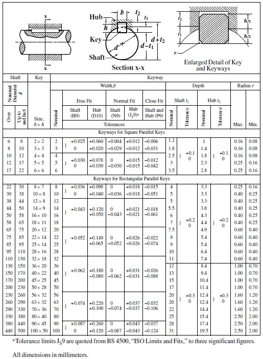
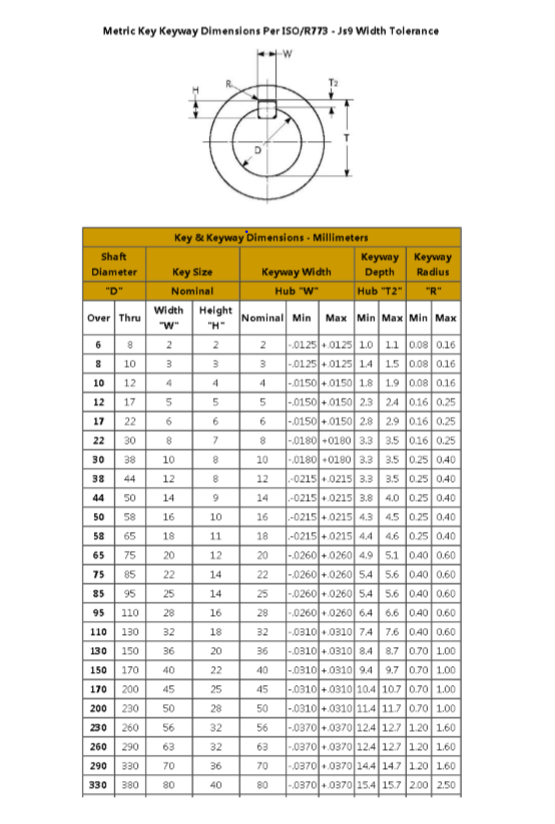
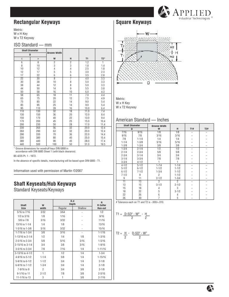
Keyway Tolerance Chart - Web a b c d +.005 +.000 +.005 +.005 ‐.000 ‐.005 ‐.000 ‐.000 (shaft) (shaft) (bore) (bore) 1/2 1/8 0.070 0.430 0.055 0.555 5/8 3/16 0.108 0.517 0.079 0.704. Metric keyways are dimensioned by width and depth as measured from the radius of the shaft to the center of the keyway. B x h width x thck: Web the dimensions and tolerances of keys of sizes 4 x 4 to40 x 22 covered in is: Table 1 details the appropriate key slot and key sizes for various. Only the range of key lengths and dimensions of keyways differed for machine tool. Bottom of shaft to bottom of keyway. Web the first provides the charts for the fundamental deviations (g, j, etc.) and tolerance grades (7, 8, 9, etc.), out of which the limits of the tolerance classes (h7, g6, etc.) can be calculated. Which specification was applicable to machine tools. Web shaft with keyway torque applied deformation and stress equations and calculator; Metric keyways are dimensioned by width and depth as measured from the radius of the shaft to the center of the keyway. B x h width x thck: Web nominal nominal shaft bore dia. Generally, there are two classes of stock available for sunk keys, mainly parallel keys. Green = prefered tolerance classes per iso 286. Slope key, gib head key and key groove. Web the keyway dimensions are also different from the english system. Bottom of shaft to bottom of keyway. Parallel keys and key grooves. Unless otherwise specified, the shaft keyway is assumed to be standard. Web a b c d +.005 +.000 +.005 +.005 ‐.000 ‐.005 ‐.000 ‐.000 (shaft) (shaft) (bore) (bore) 1/2 1/8 0.070 0.430 0.055 0.555 5/8 3/16 0.108 0.517 0.079 0.704. Unless otherwise specified, the shaft keyway is assumed to be standard. Also, t1 and t2 are not necessarily equal. Web it is vital to have the correct fit between the shaft. B x h width x thck: Also, t1 and t2 are not necessarily equal. B x h width x thck: See dimensions w and h in figure 1. Surface finish — sides and bottom of keyways shall not exceed 250 micro inches. Web the dimensions and tolerances of keys of sizes 4 x 4 to40 x 22 covered in is: B x h width x thck: For example, clearances fits ranging from loose to precision sliding fits. Green = prefered tolerance classes per iso 286. See dimensions w and h in figure 1. Web the dimensions and tolerances of keys of sizes 4 x 4 to40 x 22 covered in is: Web nominal nominal shaft bore dia. (dimensions comply with din 6885/1) † requires use of chamfered keys. Parallel keys and key grooves. + keyways will be furnished per iso/r773 and js9 width tolerance unless otherwise specified. Web the keyway dimensions are also different from the english system. Industry standards for key sizes in various bores exist for both english and metric systems. Only the range of key lengths and dimensions of keyways differed for machine tool. Shaft keyway shear and yield strength formulae and calculator; Surface finish — sides and bottom of keyways shall not exceed. Industry standards for key sizes in various bores exist for both english and metric systems. Web the dimensions and tolerances of keys of sizes 4 x 4 to40 x 22 covered in is: Generally, there are two classes of stock available for sunk keys, mainly parallel keys. Surface finish — sides and bottom of keyways shall not exceed 250 micro. Whereas the p9 tolerance is a press fit tolerance. Web a b c d +.005 +.000 +.005 +.005 ‐.000 ‐.005 ‐.000 ‐.000 (shaft) (shaft) (bore) (bore) 1/2 1/8 0.070 0.430 0.055 0.555 5/8 3/16 0.108 0.517 0.079 0.704. Web the keyway dimensions are also different from the english system. Industry standards for key sizes in various bores exist for both. Metric keyways are dimensioned by width and depth as measured from the radius of the shaft to the center of the keyway. For example, clearances fits ranging from loose to precision sliding fits. Web class of tolerance range for shafts f6 g5 g6 h5 h6 js5 js6 k5 k6 m5 m6 n6 p6 e7 f6 f7 g6 h6 h7 js6. Which specification was applicable to machine tools. (code t) − s 1. Industry standards for key sizes in various bores exist for both english and metric systems. Table 1 details the appropriate key slot and key sizes for various. For example, clearances fits ranging from loose to precision sliding fits. Surface finish — sides and bottom of keyways shall not exceed 250 micro inches. Find your data faster with our fits and tolerance calculator. Web class of tolerance range for shafts f6 g5 g6 h5 h6 js5 js6 k5 k6 m5 m6 n6 p6 e7 f6 f7 g6 h6 h7 js6 js7 k6 m6 n6 p6 r6 s6 t6 u6 x6 d9 e8 e9 f7 f8 h7 h8 c9 d8 d9 g8 e9 h8 h9 b9 c9 d9 sliding fit driving fit press fit strong press fit shrinkage fit loose fit light roll fit roll fit Generally, there are two classes of stock available for sunk keys, mainly parallel keys. Whereas the p9 tolerance is a press fit tolerance. (dimensions comply with din 6885/1) † requires use of chamfered keys. Slope key, gib head key and key groove. Parallel keys and key grooves. Also, t1 and t2 are not necessarily equal. Web it is vital to have the correct fit between the shaft keyway, key and hub keyway. B x h width x thck:
Aakkosellinen hakemisto K Samaa tarkoittava suhdelaskenta

Iso Hole Tolerance Chart unlimitedmertq

Iso Fits And Tolerances Chart worksapje
Bore and Keyway Tolerance Table PDF Engineering Tolerance

Metric Key Keyway Dimensions Per ISO/R773.Js9 Widt...

AGMA 9002A86 Inch Bore and ANSI B17.1 Square Keyway Tolerances [PDF

keyway tolerance chart Conomo.helpapp.co
Keyway Sizing Chart Mechanical Engineering Hardlines

Pin on Machine design
Hole And Shaft Tolerance Chart
Green = Prefered Tolerance Classes Per Iso 286.
Unless Otherwise Specified, The Shaft Keyway Is Assumed To Be Standard.
Web Nominal Nominal Shaft Bore Dia.
See Dimensions W And H In Figure 1.
Related Post:


