Maf Sensor Voltage Chart
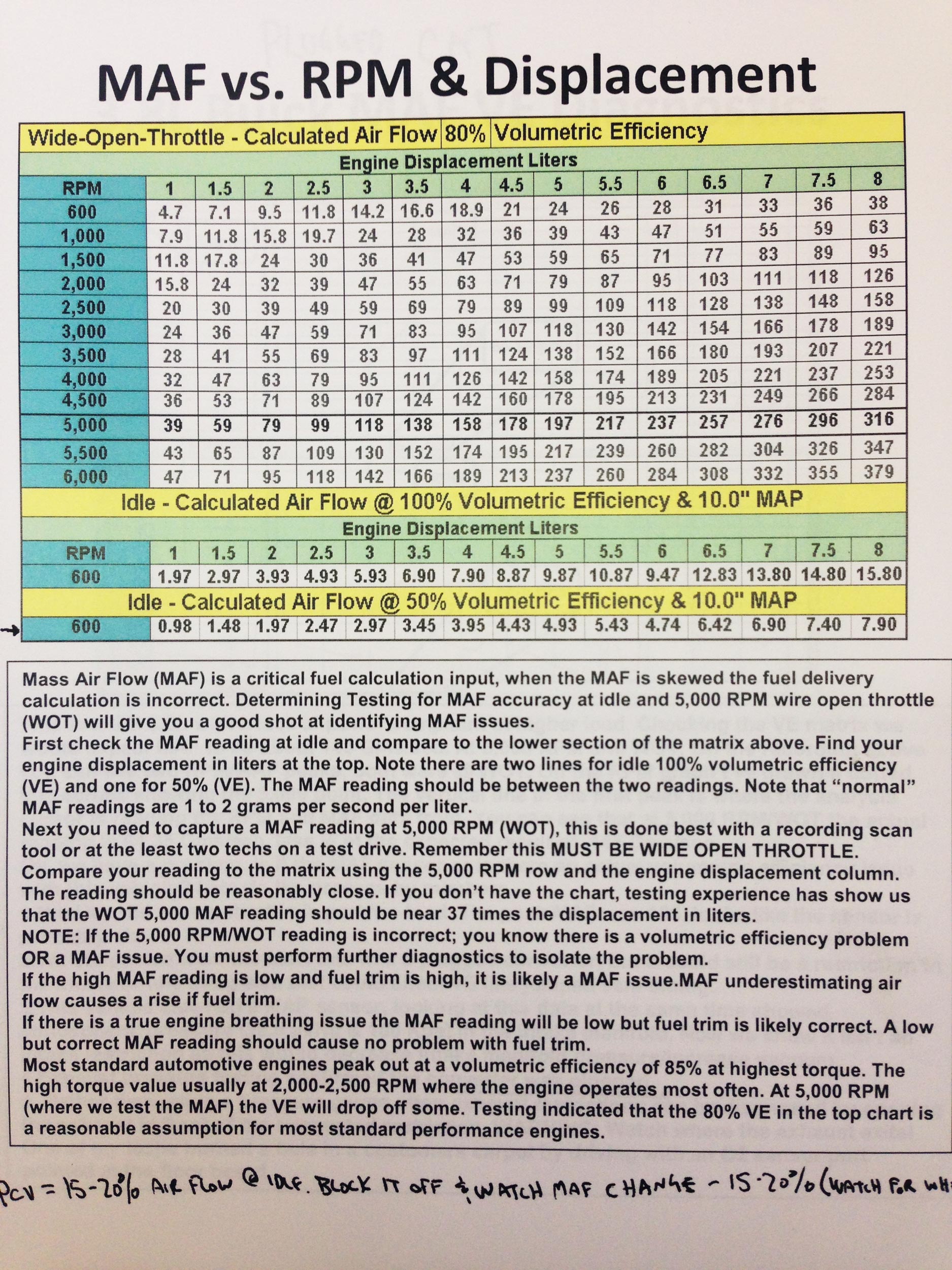
Maf Sensor Voltage Chart - Circuit descriptions of the maf sensor connector. The speed density method is a little more complicated. Web all you'll need, to test the maf sensor (with this tutorial) is a multimeter that can read hertz frequency (if you don't have one, i've made a recommendation on where you can buy a reasonably priced one below). Symptoms of a bad or. Web this requires using a wiring diagram (of the fuel system management system) to be able to know which wire is the one that feeds 12 volts, which one is the that feeds ground, and which one is the one that carries the maf signal to the fuel injection computer. Web correct functioning of the hot wire air mass sensor sensor with frequency output can be checked by measuring the following signal voltages, see figure 1: What tools do i need? The electrical signal is transmitted to the engine control module and is used to determine the required fueling for gas engines and for exhaust gas recirculation (egr) control on diesel engines. This is accomplished by connecting a resistor to the signal wire of the maf sensor, which alters its resistance and, as a result, the voltage signal the maf sensor sends to the ecu. Web a general rule of thumb is voltage should exceed 4 volts. However, there is a flaw with this test when used on a vehicle with electronic throttle control. At 3,000 rpm, the voltage output should be between 8.0 and 22.0 volts. Web when performing these tests, try checking for a voltage signal; With four basic tests, you'll quickly determine if the maf sensor is good or bad. What tools do i. Symptoms of a bad maf sensor. The following hierarchical diagram below shows how the afm sensors are subdivided according to the vehicle/fuel type: Symptoms of a bad or. Web mass air flow sensors provide a voltage signal, corresponding to the air mass entering the engine. Circuit descriptions of the maf sensor connector. A contaminated or bad air flow sensor will, in most cases, show lower air flow readings than a known good one. Often mass air flow sensor readings are measured at idle, 1,000 rpm, 2,000 rpm and 3,000 rpm. Find out how to test a maf sensor and how to replace a defective one with these tips from our mechanics. The. One cycle is made when the o2 sensor signal crosses the 0.45v point approximately 3 times (3 cross counts). Web the mass air flow (maf) sensor measures the weight of the air entering the engine, and the ecm controls the fuel injectors to achieve the correct air/fuel ratio. Some will provide specifications at several engine speeds. Web mass air flow. In this tutorial, i'll explain how to test it with a multimeter. Often mass air flow sensor readings are measured at idle, 1,000 rpm, 2,000 rpm and 3,000 rpm. Circuit descriptions of the maf sensor connector. The air mass information is necessary for the engine control unit (ecu) to balance and deliver the correct fuel mass to the engine. Web. This is accomplished by connecting a resistor to the signal wire of the maf sensor, which alters its resistance and, as a result, the voltage signal the maf sensor sends to the ecu. Symptoms of a bad gm maf sensor. With four basic tests, you'll quickly determine if the maf sensor is good or bad. Find out how to test. Web the mass air flow (maf) sensor reads the air flow entering the engine. When the o2 sensor signal stuck at 0.45v. With four basic tests, you'll quickly determine if the maf sensor is good or bad. Web with the engine at idle, the maf’s pid value should read anywhere from 2 to 7 grams/second (g/s) at idle and rise. This is accomplished by connecting a resistor to the signal wire of the maf sensor, which alters its resistance and, as a result, the voltage signal the maf sensor sends to the ecu. Web the voltage signal should also go higher than 0.75v and lower than 0.25v. Web this requires using a wiring diagram (of the fuel system management system). Web correct functioning of the hot wire air mass sensor sensor with frequency output can be checked by measuring the following signal voltages, see figure 1: The electrical signal is transmitted to the engine control module and is used to determine the required fueling for gas engines and for exhaust gas recirculation (egr) control on diesel engines. On a vehicle. When the o2 sensor signal stuck at 0.45v. On a vehicle with a cabled throttle this test works quite well. Web this requires using a wiring diagram (of the fuel system management system) to be able to know which wire is the one that feeds 12 volts, which one is the that feeds ground, and which one is the one. Symptoms of a bad gm maf sensor. Web depending on your maf sensor, your voltage reading should be between 0.60 to 0.80 volts at idle. However, there is a flaw with this test when used on a vehicle with electronic throttle control. The following hierarchical diagram below shows how the afm sensors are subdivided according to the vehicle/fuel type: A defective maf sensor can cause engine stalling, a rough running engine, and a check engine light for trouble codes like code p0171. Some will provide specifications at several engine speeds. Often mass air flow sensor readings are measured at idle, 1,000 rpm, 2,000 rpm and 3,000 rpm. This is accomplished by connecting a resistor to the signal wire of the maf sensor, which alters its resistance and, as a result, the voltage signal the maf sensor sends to the ecu. Find out how to test a maf sensor and how to replace a defective one with these tips from our mechanics. Web when performing these tests, try checking for a voltage signal; Air changes its density with temperature and pressure. How to test a maf sensor using. The speed density method is a little more complicated. How it works, common symptoms of failure, diagnostic methods, and testing with a multimeter. Symptoms of a bad or. Web understanding the mass air flow sensor (maf):
Experimental values output of air flow (MP 200) and voltage of MAF

What are the two wire on the 6 wire IAT / MAF sensor connector that

Weekly waveform 17 recap analog MAF sensor voltage YouTube

Understanding MAF Sensor Readings Blazer Forum Chevy Blazer Forums

Maf Sensor Voltage Chart

Repair Guides Components & Systems Mass Air Flow (maf) Sensor
Mass Air Flow Sensor Wiring Diagram

Subaru Airbox MAF Flow Test

Gears Magazine MAF Sensor Diagnosis

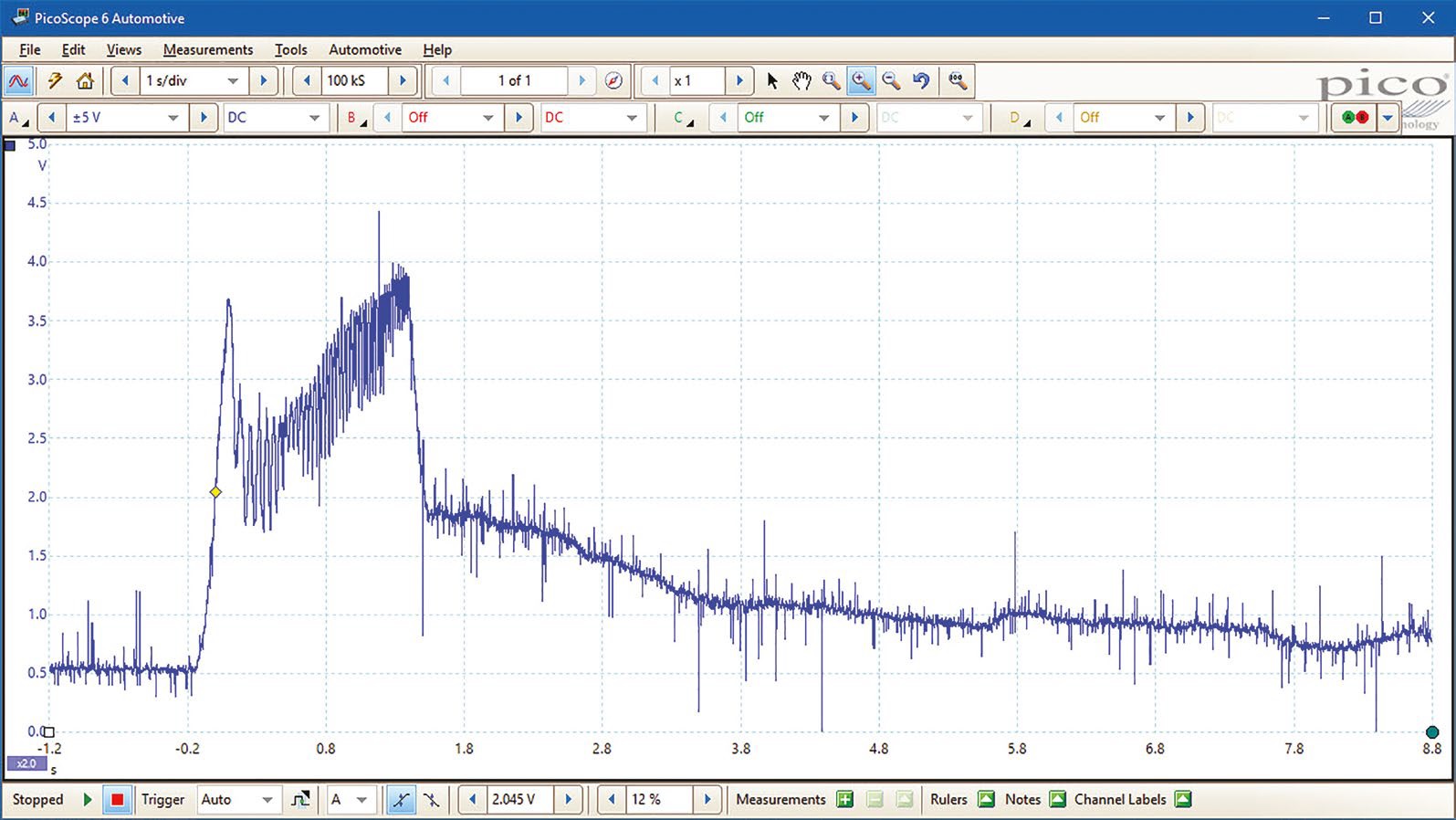
Snap Wide Open Throttle Test of a Mass Airflow Sensor
In This Tutorial, I'll Explain How To Test It With A Multimeter.
If Your Reading Indicates 12 Volts Or Pretty Close To It, You Are Probing The Power Wire, Not The Signal Wire).
At 3,000 Rpm, The Voltage Output Should Be Between 8.0 And 22.0 Volts.
Web Correct Functioning Of The Hot Wire Air Mass Sensor Sensor With Frequency Output Can Be Checked By Measuring The Following Signal Voltages, See Figure 1:
Related Post: