Mechanical Object Drawing
Mechanical Object Drawing - Web any engineering drawing should show everything: Web 28k views 2 years ago. Water and wastewater system design. Mechanical engineering drawing is the art of representing mechanical engineering objects on paper, such as machines, machine parts, and so on. Engineering drawings use standardised language and symbols. This makes understanding the drawings simple with little to no personal interpretation possibilities. Web mechanical drafting, also known as mechanical drawing, is a crucial aspect of mechanical engineering and related fields. Web mechanical engineering drawings are used to define the requirements for engineering products/components. All projection theory is based on two variables: Web autocad is a powerful software tool used by engineers and designers to create precise and accurate mechanical drawings. It is more than simply a drawing, it is a graphical language that communicates ideas and information. Mechanical engineering drawing is the art of representing mechanical engineering objects on paper, such as machines, machine parts, and so on. Mechanical engineering drawings can be divided into four main categories: Engineering drawings use standardised language and symbols. The drawing you have opened. Mechanical engineering drawings can be divided into four main categories: Web an engineering drawing (also named as mechanical drawing, manufacturing blueprints, drawings, dimensional prints, and more) refers to one of the technical drawings, which helps to define engineering products’ requirements. Machine drawing is a field of engineering graphics that determines the shapes and sizes of machines and their components. Web. Technical drawing is essential for communicating ideas in industry and engineering. The two main types of views (or “projections”) used in drawings are: The how do you draw robots tutorial. Machine drawings are essential for manufacturing, assembling, and maintaining machines. You can also search for and participate in art competitions. The purpose is to convey all the information necessary for manufacturing a product or a part. Web graphics communications are used in every phase of engineering design starting from concept illustration all the way to the manufacturing phase. Whether you are a beginner or an experienced user, it is essential to have a solid understanding of the basics before diving. Water and wastewater system design. The two main types of views (or “projections”) used in drawings are: It helps to define the requirements of an engineering part and conveys the design. Mechanical engineers use it to express mechanical engineering works and projects for actual execution. Learn how to draw mechs or whatever you want really, i dunno, just draw something.extra. All projection theory is based on two variables: It involves the use of specialized software tools and manual skills to create detailed and precise 2d or 3d representations of physical parts, components, and assemblies. It is more than simply a drawing, it is a graphical language that communicates ideas and information. Web any engineering drawing should show everything: Web the. Line of sigh t (projecting lines) and plane of projection. If the isometric drawing can show all details and all dimensions on one drawing, it is ideal. Web technical drawing, drafting or drawing, is the act and discipline of composing drawings that visually communicate how something functions or is constructed. It involves the use of specialized software tools and manual. Web autocad is a powerful software tool used by engineers and designers to create precise and accurate mechanical drawings. A line of sight (los) is an imaginary line between an observer’s eye and an object. It is used to communicate the design intent of engineers and manufacturers. Web engineering drawings (aka blueprints, prints, drawings, mechanical drawings) are a rich and. Web 28k views 2 years ago. Web engineering drawings, also known as mechanical drawings, manufacturing blueprints, drawings, etc., are technical drawings that show the shape, structure, dimensions, tolerances, accuracy, and other requirements of a part in the form of a plan. It is more than simply a drawing, it is a graphical language that communicates ideas and information. Basically, this. Mechanical engineering drawings can be divided into four main categories: Web any engineering drawing should show everything: It involves the use of specialized software tools and manual skills to create detailed and precise 2d or 3d representations of physical parts, components, and assemblies. Web an engineering drawing (also named as mechanical drawing, manufacturing blueprints, drawings, dimensional prints, and more) refers. Web mechanical drafting, also known as mechanical drawing, is a crucial aspect of mechanical engineering and related fields. All projection theory is based on two variables: The purpose is to convey all the information necessary for manufacturing a product or a part. This makes understanding the drawings simple with little to no personal interpretation possibilities. Try drawing complex subject matter, like hair underwater, an intricate mechanical object, or your favorite dishes. The two main types of views (or “projections”) used in drawings are: Standards and specifications visualize 2d mechanical objects using iso, ansi, bsi, csn, din, gb and jis standards. Mechanical drawings rely on precise mathematical equations to accurately depict the mechanism and it component parts. Technical drawing is essential for communicating ideas in industry and engineering. The drawing you have opened or referenced contains custom objects created by an unavailable objectarx application. This time we see how we can combine knowledge from technical drawing and perspective tricks to recreate objects. Why not just use a 3d model? It is used to communicate the design intent of engineers and manufacturers. Web types of views used in drawings. A line of sight (los) is an imaginary line between an observer’s eye and an object. An engineering (or technical) drawingis a graphical representation of a part, assembly, system, or structure and it can be produced using freehand, mechanical tools, or computer methods.
Mechanical Object Drawing

Autocad Mechanical 3d Drawings For Practice

Image result for detailed assembly drawing Autocad isometric drawing

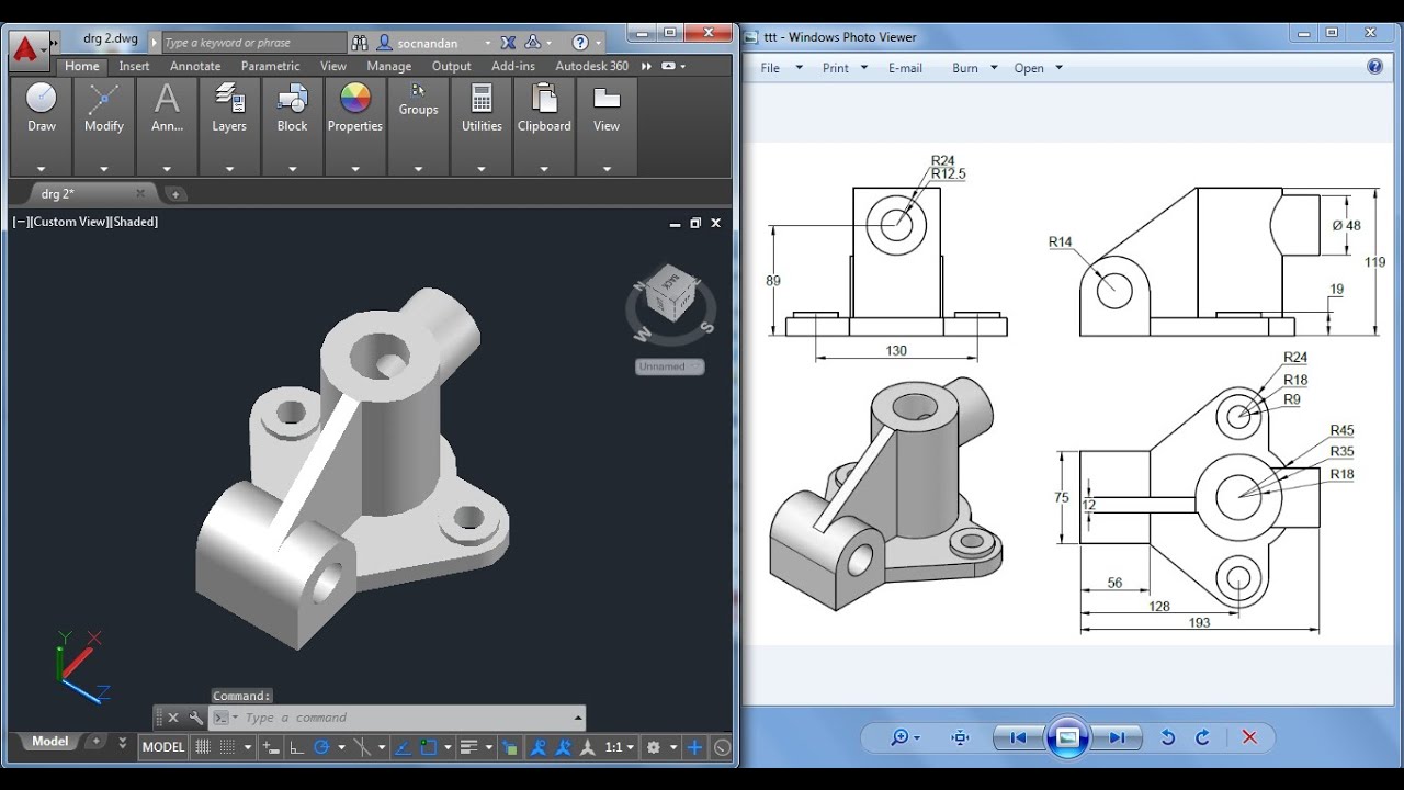
How to Draw Mechanical object in AutoCAD 3D Tutorial2 for Beginners

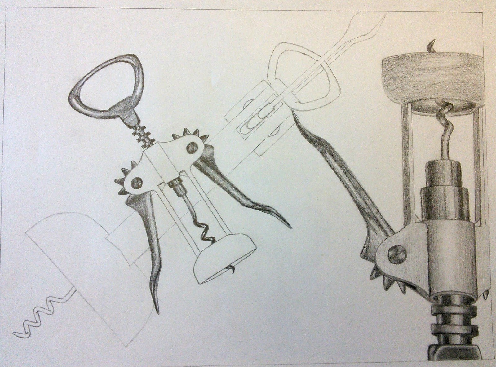
drawing mechanical objects Google Search Mechanical Object Drawing

Starting to Draw Mechanical objects

technical mechanical drawing Google Search Metal Drawing, Drawing

AutoCAD 3D Practice Mechanical Drawing using Box & Cylinder Command

Autocad Mechanical Drawings Samples at Explore

Autocad Mechanical Drawing at GetDrawings Free download
The How Do You Draw Robots Tutorial.
Web An Engineering Drawing (Also Named As Mechanical Drawing, Manufacturing Blueprints, Drawings, Dimensional Prints, And More) Refers To One Of The Technical Drawings, Which Helps To Define Engineering Products’ Requirements.
You Can Even Flip Between Scales On The Fly.
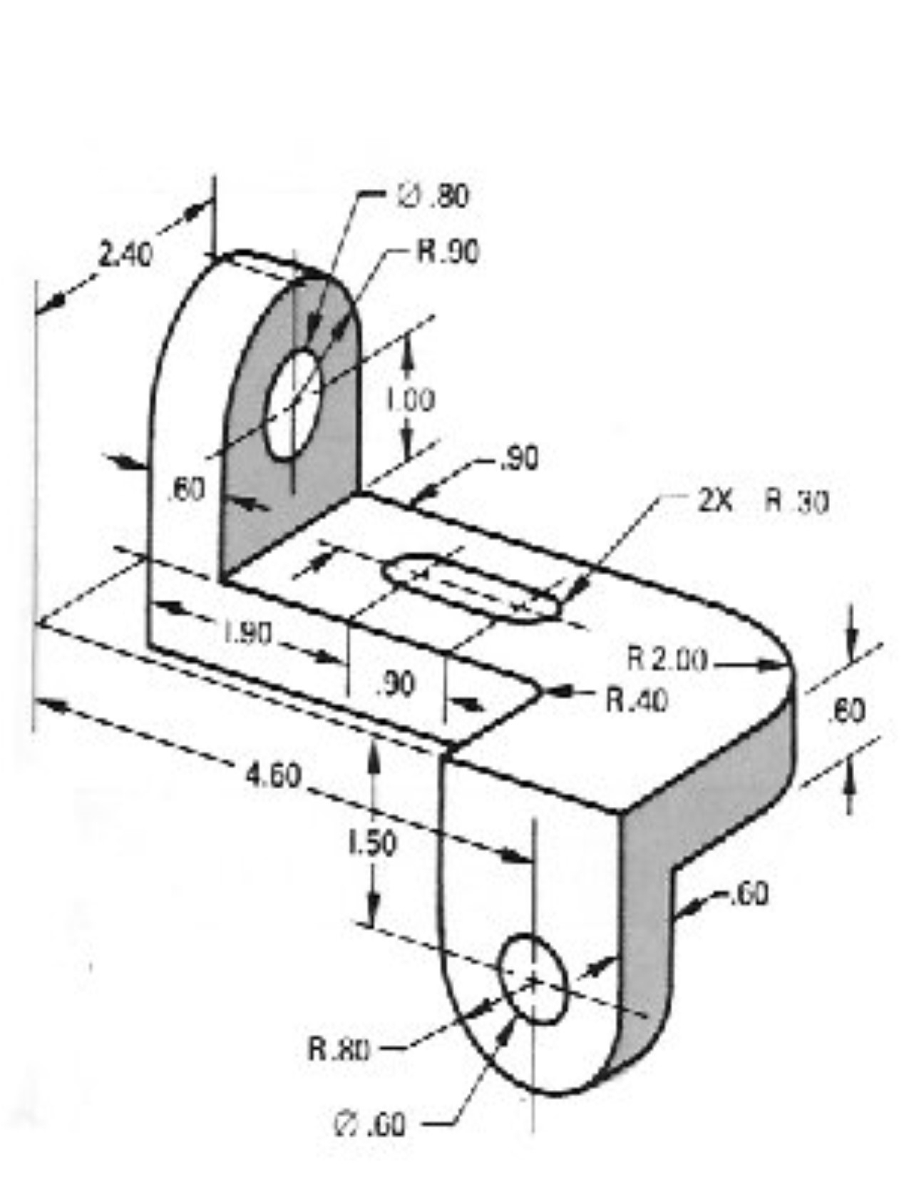
If The Isometric Drawing Can Show All Details And All Dimensions On One Drawing, It Is Ideal.
Related Post: