Pipe Fittings Drawing Symbols
Pipe Fittings Drawing Symbols - These symbols cover all sorts of plumbing tools and equipment. A legend of symbols used in piping and plumbing drafting. Web this is an isometric pipe drawing that explains how to identify the fittings in the interview, the client can ask you, by counting the material in it, show which material is used in so many pieces there is an end cap at the beginning of the line, from here the line is starting total 1 end cap is installed Web piping symbols are important to read drawings as it gives quick reference about fittings, joint types, valve types and any other special component to be used. There may be multiple symbols for one fitting or part depending on the fashion it is to be installed (butt weld, socket weld, threaded.) Fitter training 27/12/2021 0 comments fluid codes, fluid codes for drawing, line numbering, line symbols, p & id connectors, piping symbols, piping abbreviation, process blowdown, valve symnols. Lines piping components (pipes, flanges, and fittings) valves filters instruments and instrumentation pumps compressors vessels electrical machines (motors, generators, and turbines) heat exchangers lines p&id symbols piping p&id symbols valves p&id. In this article 01 what are the plumbing symbols 02 the types of plumbing. An elbow is a fitting that changes the direction of the flow. 6 provides symbols for plumbing components. Web here are some of the common piping symbols for fittings: Web piping symbols are important to read drawings as it gives quick reference about fittings, joint types, valve types and any other special component to be used. Symbols are shown in black lines. Web this part of bs 1553 specifies graphical symbols for use in flow and piping diagrams. Symbols for single line piping arrangements. Bell and flanged screwed spigot. Web this is an isometric pipe drawing that explains how to identify the fittings in the interview, the client can ask you, by counting the material in it, show which material is used in so many pieces there is an end cap at the beginning of the line, from. Web in this video we explain about the important symbols that are used for pipe joint and fittings in engineering drawing. Fittings, flanges, and valves play essential roles in pipeline isometric drawings, each with unique symbols according to iso standards. Web this part of bs 1553 specifies graphical symbols for use in flow and piping diagrams for process plant. And. Symbols are shown in black lines. Web this is an isometric pipe drawing that explains how to identify the fittings in the interview, the client can ask you, by counting the material in it, show which material is used in so many pieces there is an end cap at the beginning of the line, from here the line is starting. Web in this video we explain about the important symbols that are used for pipe joint and fittings in engineering drawing. These are fundamental to every standardized engineering project. Web this part of bs 1553 specifies graphical symbols for use in flow and piping diagrams for process plant. Web isometric drawing symbols for piping fittings. Web p&id is an abbreviation. Pressure, temperature, flow, level, switches, alarms, and miscellaneous. A legend of symbols used in piping and plumbing drafting. In this article 01 what are the plumbing symbols 02 the types of plumbing. Bell and flanged screwed spigot. Web various symbols are used to indicate piping components, instrumentation, equipments in engineering drawings such as piping and instrumentation diagram (p&id), isometric drawings,. Web piping symbols are important to read drawings as it gives quick reference about fittings, joint types, valve types and any other special component to be used. Web in this video we explain about the important symbols that are used for pipe joint and fittings in engineering drawing. Bell and flanged screwed spigot. Lighter lines show connected pipe, and are. For example if a 90 degree elbow is to be placed in service the drawing will reflect a 90 degree angle. 5 provides symbols for fans, pumps, and turbines. When the pipe doesn’t move in the exact north, south, east, or west direction then the movement is shown with help of rolling angles. *also used for general stop valve when. Symbols are shown in black lines. Post cad drafting jobs on freelancer.com. Lighter lines show connected pipe, and are not parts of the symbols. Piping and instrumentation diagrams are graphical representations of a process system. Web piping symbols are important to read drawings as it gives quick reference about fittings, joint types, valve types and any other special component to. Web p&id is an abbreviation meaning ‘ piping and instrumentation diagram ‘. Web piping symbols serve as the alphabet of isometric drawings, with each symbol representing a specific component, similar to words in a language. 5 provides symbols for fans, pumps, and turbines. Web piping and instrument diagram standard symbols detailed documentation provides a standard set of shapes & symbols. Web piping symbols are important to read drawings as it gives quick reference about fittings, joint types, valve types and any other special component to be used. Symbols are shown in black lines. Web this part of bs 1553 specifies graphical symbols for use in flow and piping diagrams for process plant. 5 provides symbols for fans, pumps, and turbines. Web piping and plumbing symbols list. A free autocad block download, in dwg format. Web various symbols are used to indicate piping components, instrumentation, equipments in engineering drawings such as piping and instrumentation diagram (p&id), isometric drawings, plot plan, equipment layout, welding drawings etc. Web the most common p&id symbols are listed below: 7 provides symbols for pipe and pipe fittings. Web piping and instrument diagram standard symbols detailed documentation provides a standard set of shapes & symbols for documenting p&id and pfd, including standard shapes of instrument, valves, pump, heating exchanges, mixers, crushers, vessels, compressors, filters, motors and connecting shapes. Web there may be multiple symbols for one fitting or part depending on the fashion it is to be installed (butt weld, socket weld, threaded.) below is a breakdown of almost every type of fitting and connection. Web in this video we explain about the important symbols that are used for pipe joint and fittings in engineering drawing. This topic is taken from iti first yea. Web isometric drawing symbols for piping fittings. Bell and flanged screwed spigot. Web here are some of the common piping symbols for fittings: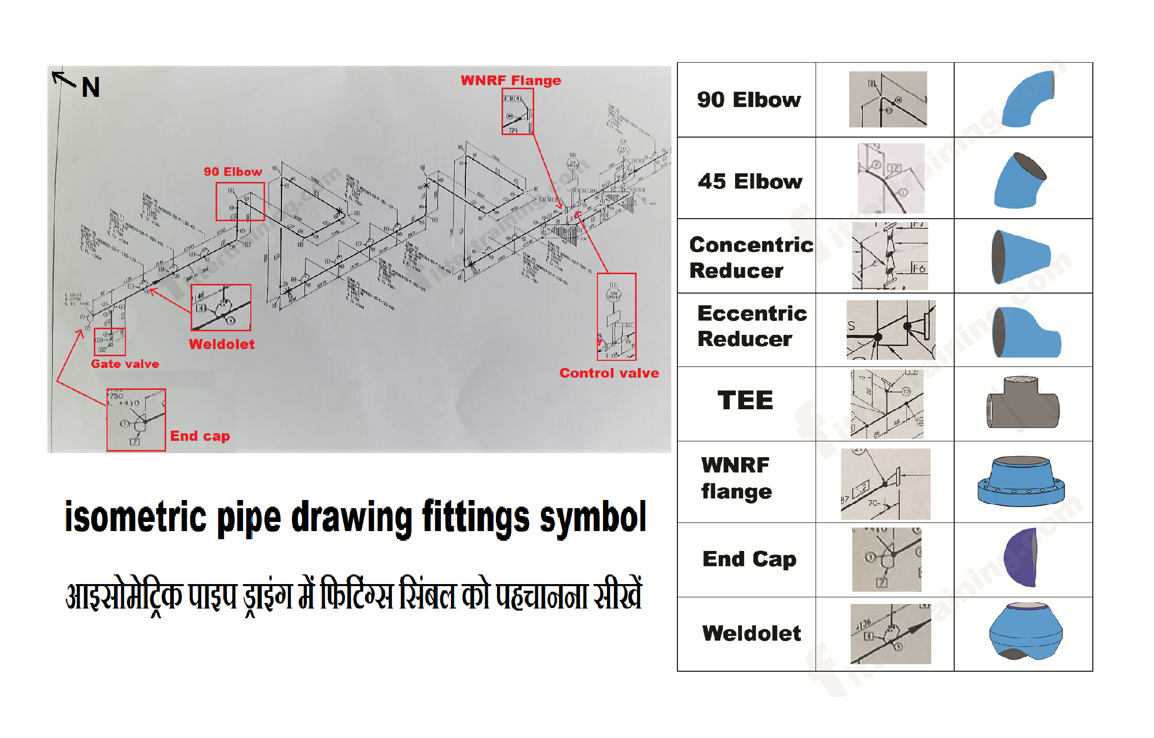
isometric pipe drawing fittings symbol Fitter training

PIPE FITTING ISOMETRIC Free CAD Block Symbols And CAD Drawing
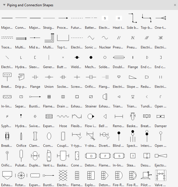
Plumbing and Piping Plan Symbols Edraw

Pipe Fitting Symbols
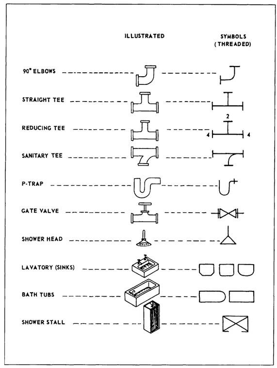
Isometric symbols for piping pdf liotru
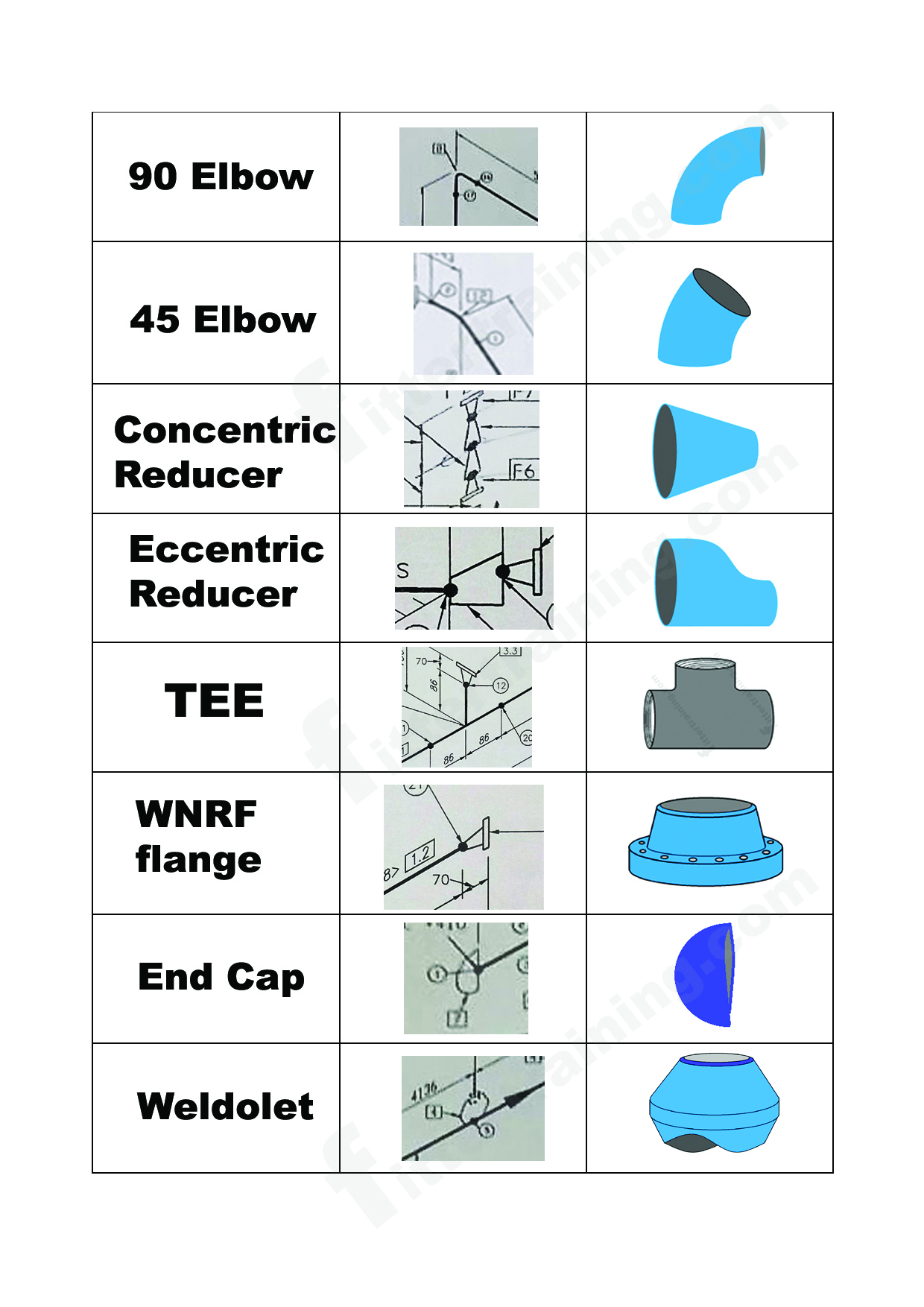
isometric pipe drawing fittings symbol Fitter training
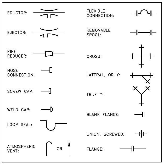
Piping and Instrumentation Symbols Instrumentation Tools

Basic Piping Isometric Symbols Piping Analysis YouTube
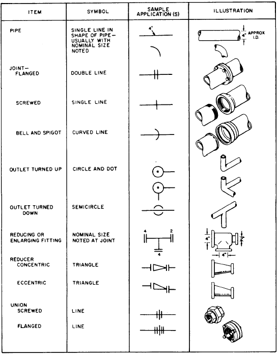
Fitting symbols

What is Piping Isometric drawing? How to Read Piping Drawing? ALL
Web P&Id Is An Abbreviation Meaning ‘ Piping And Instrumentation Diagram ‘.
These Are Fundamental To Every Standardized Engineering Project.
Web P & I D Piping Drawing Fittings Symbols Pdf Chart.
Lines Piping Components (Pipes, Flanges, And Fittings) Valves Filters Instruments And Instrumentation Pumps Compressors Vessels Electrical Machines (Motors, Generators, And Turbines) Heat Exchangers Lines P&Id Symbols Piping P&Id Symbols Valves P&Id.
Related Post: