Piping Isometric Drawing
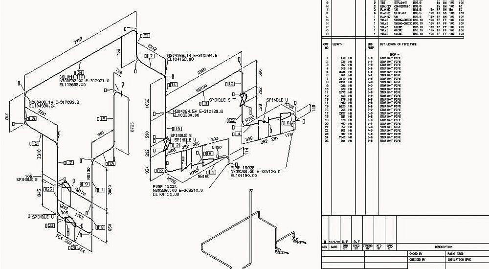
Piping Isometric Drawing - This part of the chapter focuses on the methods for identifying these. Web piping isometric drawing consists of three sections. The historical absence of isometric view drawings and visualizations had significant consequences. Pipes are shown in the same size. Pipes are drawn with a single line irrespective of the line sizes, as well as the other configurations such as reducers,. The main body of a piping isometric drawing is consist of:. With the help of sophisticated computer aided design (cad) tools, piping engineers and designers can produce isometric drawings from 3d models with ease. Web features of piping isometric drawing it is not drawn to the scale, but it is proportionate with the exact dimensions represented. The symbols that represent fittings, valves and flanges are modified to adapt to the isometric grid. Second, draw the pipeline with the help of simple lines. All isometric drawings are created regardless of the size and length of the lines and the piping components, but this. Π x diameter of the. Automated bill of materials no more tedious material tracking when creating a pipe isometric drawing. Web 42k views 1 year ago tutorials for pipe fitters and fabricators. They serve as precise illustrations providing essential information. The historical absence of isometric view drawings and visualizations had significant consequences. Easy isometric interface import idf or pcf files allows for flexible drawing track spools spoolfab's inventory system enables the automatic inventorying and subsequent generation of reports such as: Web features of piping isometric drawing it is not drawn to the scale, but it is proportionate with the exact. In the context of pipeline design and engineering, isometric drawings have assumed a significant role. How to read iso drawings. Create a drawing sheet for isometrics. Reading a piping isometric drawing basic training. Web the isometrics drawing are created from information found on a plan and elevation views. All isometric drawings are created regardless of the size and length of the lines and the piping components, but this. Draw the route of the pipeline. The symbols that represent fittings, valves and flanges are modified to adapt to the isometric grid. Web the isometrics drawing are created from information found on a plan and elevation views. Web create the. Web piping isometric drawing consists of three sections. With the help of sophisticated computer aided design (cad) tools, piping engineers and designers can produce isometric drawings from 3d models with ease. How to read iso drawings. Create a drawing sheet for isometrics. Web isometric drawings, often referred to as isometrics, are a type of 3d representation that offers a unique. In this article, a few of the salient points are discussed. First create a drawing sheet in din a4 or a3 and activate the isometric grid. Create a drawing sheet for isometrics. Unlike orthographic drawings that show different views (front, side, and top) separately, isometric drawings combine these views into a. The historical absence of isometric view drawings and visualizations. In the context of pipeline design and engineering, isometric drawings have assumed a significant role. The piping isometric drawing serves as a „mediator“ between planner and engineer. Web what is piping isometric drawing? The principal dimensions are the limits of size for the object along the three principal directions. Are tagged with the same codes used on the p&id and. Pipes are shown in the same size. Unlike orthographic drawings that show different views (front, side, and top) separately, isometric drawings combine these views into a. So engineers and designers must be aware of the isometric preparation steps. Web create isometric drawings in minutes: Web features of piping isometric drawings a person can visualize a 3d view of a line. Web features of piping isometric drawing it is not drawn to the scale, but it is proportionate with the exact dimensions represented. The piping isometric drawing serves as a „mediator“ between planner and engineer. Unlike orthographic drawings that show different views (front, side, and top) separately, isometric drawings combine these views into a. Are tagged with the same codes used. Bottom section of isometric drawing contains:. Web create the piping isometric drawing manually 1. Web an isometric drawing is a type of pictorial drawing in which three sides of an object can be seen in one view. Section of left or right of piping isometric drawing includes:. Web piping isometric drawing is one of the most important deliverables of the. Π x diameter of the. They are not realistic, pipes are shown as single lines, and symbols are used to represent pipe fittings, valves, pipe gradients, welds, etc. Web 42k views 1 year ago tutorials for pipe fitters and fabricators. Unlike orthographic drawings that show different views (front, side, and top) separately, isometric drawings combine these views into a. They serve as precise illustrations providing essential information about the layout, dimensions, materials, and key components of a pipeline system. Create a drawing sheet for isometrics. Web a piping isometric drawing is a technical illustration that presents a 3d representation of a piping system. The main body of a piping isometric drawing is consist of:. With the help of sophisticated computer aided design (cad) tools, piping engineers and designers can produce isometric drawings from 3d models with ease. Pipes are drawn with a single line irrespective of the line sizes, as well as the other configurations such as reducers,. The piping isometric drawing serves as a „mediator“ between planner and engineer. Automated bill of materials no more tedious material tracking when creating a pipe isometric drawing. Web what is piping isometric drawing? Draw the route of the pipeline. Pipes are shown in the same size. Web piping isometrics drawing are a type of pictorial drawings that show the three principal dimensions of an object in one view.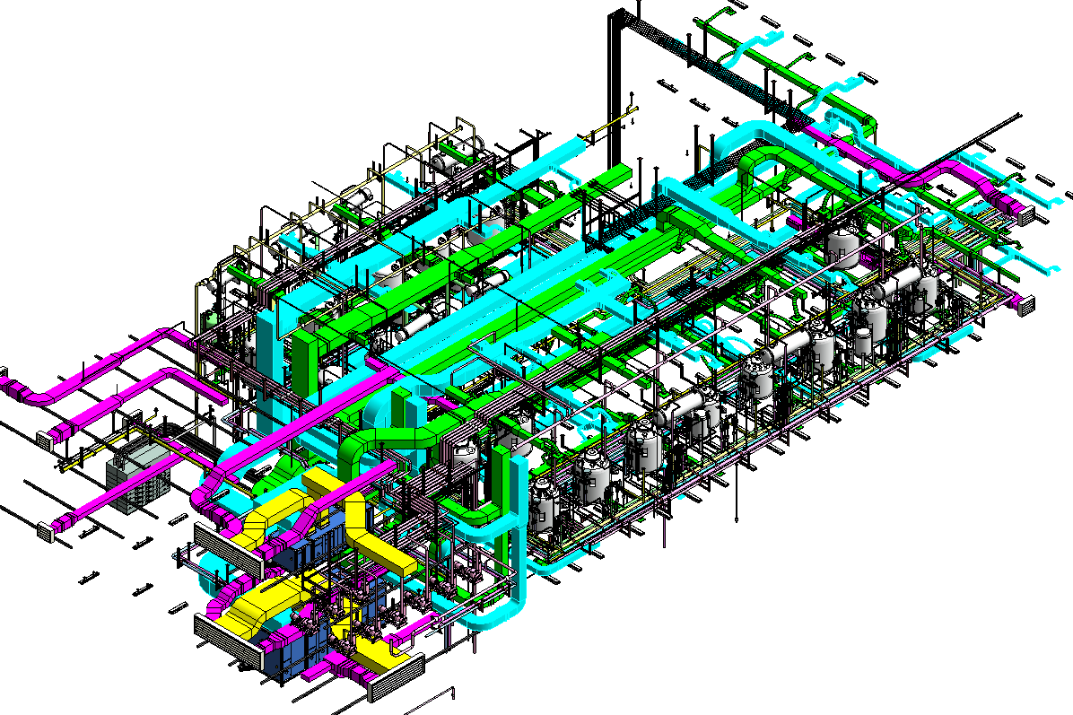
Revit AddOns EzISO Piping Models to Isometric Drawings

Piping isometric drawing examples mazorama

Piping Isometric Drawing at Explore collection of
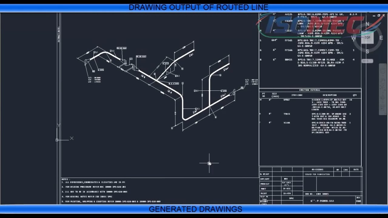
Piping Isometric Drawing at Explore collection of
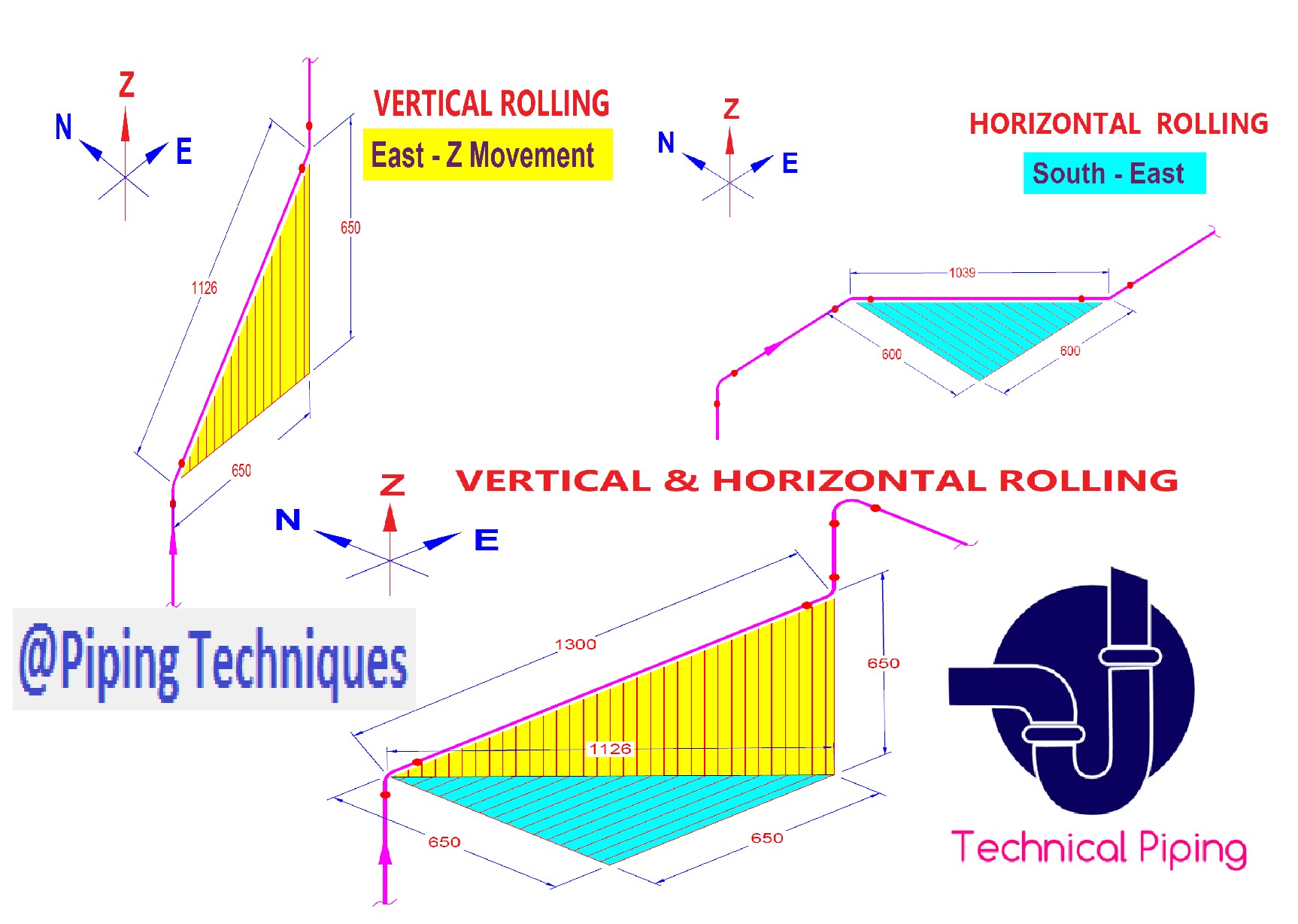
Piping Isometric Drawing Exercises Pdf at GetDrawings Free download

Learn isometric drawings (piping isometric)

Isometric Piping Drawings Advenser

Piping Design Basics Piping Isometric Drawings Piping Isometrics
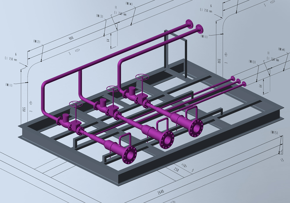
Automatic Piping Isometrics from 3D Piping Designs M4 ISO
Automatic Piping Isometrics from 3D Piping Designs M4 ISO
Isometric Drawings Are Typically Used To Show The Details Of A Piping System, Such As The Size And Type Of Piping, The Direction Of Flow Of The Fluids, And The Location Of Valves, Pumps, And Other Equipment Nozzles.
The Principal Dimensions Are The Limits Of Size For The Object Along The Three Principal Directions.
How To Read Piping Isometric Drawing Symbols.
Web Piping Isometric Drawings Are Rich In Information About The Various Components And Connections Within A Piping System.
Related Post: