Press Fit Bushing Tolerance Chart
Press Fit Bushing Tolerance Chart - Also, the id tolerance is 0.065 mm after installation. All tolerances classes and sizes according to standard. Find your data faster with our fits calculator. Web the chart and diagram shows that after installation this bushing will have a total od tolerance of 0.030 mm. Fixing a coupling flange and a shaft together (high torque). Web in most installations diametric interference of.0005 to.0008 is adequate for installation of press fit bushings or liners. Web use this calculator to determine the proper installation hole size for standard press fit bushings. Go here, for explanasions about the terms hole, shaft, ei, and. Web class v locational interference tolerance chart for holes and bolts. The effective interference of the press fit is. The effective interference of the press fit is. Go here, for explanasions about the terms hole,. Find out the factors influencing tolerances, tools. Hard to disassemble without damaging the components. Web the appropriate values for shaft seats are listed for the following tolerance classes: Insertion of a suction valve and valve guide. Go here, for explanasions about the terms hole, shaft, ei, and es. Web in most installations diametric interference of.0005 to.0008 is adequate for installation of press fit bushings or liners. Find your data faster with our fits calculator. Preferred tolerances and fits charts (ansi) precision measuring tools for shaft and hole measurements; Insertion of a suction valve and valve guide. Web sliding fit driving fit press fit strong press fit shrinkage fit loose fit light roll fit roll fit 50 0 −50 −100 −150 −200 dimension tolerance h6 h7 200 150 100 50 0 −50 Go here, for explanasions about the terms hole, shaft, ei, and es. Also, the id tolerance is. Fixing a coupling flange and a shaft together (high torque). Find your data faster with our fits calculator. To maximize hole accuracy and minimize. F5, f6, g5, g6, h5 ( table 1) h6, h8, h9, j5, j6 ( table 2) js4, js5, js6, js7, k4 ( table 3) k5, k6, m5, m6, n5 ( table 4) n6, p6, p7, r6,. Web class v locational interference tolerance chart for holes and bolts. Web sliding fit driving fit press fit strong press fit shrinkage fit loose fit light roll fit roll fit 50 0 −50 −100 −150 −200 dimension tolerance h6 h7 200 150 100 50 0 −50 Find your data faster with our fits calculator. Go here, for explanasions about the. Find your data faster with our fits calculator. Web sliding fit driving fit press fit strong press fit shrinkage fit loose fit light roll fit roll fit 50 0 −50 −100 −150 −200 dimension tolerance h6 h7 200 150 100 50 0 −50 Web use this calculator to determine the proper installation hole size for standard press fit bushings. Also,. Fixing a gear and a shaft together (low torque) shaft of a flexible coupling and a gear (drive side) functional classification. Find your data faster with our fits calculator. F5, f6, g5, g6, h5 ( table 1) h6, h8, h9, j5, j6 ( table 2) js4, js5, js6, js7, k4 ( table 3) k5, k6, m5, m6, n5 ( table. Web interference (press & shrink) fit calculator; See technical information on id and od tolerances, material, heat treatment, finish and more. Fixing a gear and a shaft together (low torque) shaft of a flexible coupling and a gear (drive side) functional classification. The effective interference of the press fit is. Go here, for explanasions about the terms hole, shaft, ei,. Complete charts for h7/t6 press. Web engineering, manufacturing tolerance limits fits charts. To maximize hole accuracy and minimize. Bushing and plain bearings press or shrink fit design and application. Web the chart and diagram shows that after installation this bushing will have a total od tolerance of 0.030 mm. Complete charts for h7/t6 press. Find your data faster with our fits calculator. Find your data faster with our fits calculator. Bushing and plain bearings press or shrink fit design and application. Attaching and fixing a bearing bushing. Web class v locational interference tolerance chart for holes and bolts. Also, the id tolerance is 0.065 mm after installation. Fixing a gear and a shaft together (low torque) shaft of a flexible coupling and a gear (drive side) functional classification. Complete charts for h7/t6 press. Find out the factors influencing tolerances, tools. Web the chart and diagram shows that after installation this bushing will have a total od tolerance of 0.030 mm. See technical information on id and od tolerances, material, heat treatment, finish and more. All tolerances classes and sizes according to standard. Preferred force shrink fits chart. F5, f6, g5, g6, h5 ( table 1) h6, h8, h9, j5, j6 ( table 2) js4, js5, js6, js7, k4 ( table 3) k5, k6, m5, m6, n5 ( table 4) n6, p6, p7, r6, r7 ( table 5) r6+it6, r7+it7 ( table 6) Insertion of a suction valve and valve guide. To maximize hole accuracy and minimize. Find your data faster with our fits calculator. Go here, for explanasions about the terms hole, shaft, ei, and es. Fixing a coupling flange and a shaft together (high torque). The effective interference of the press fit is.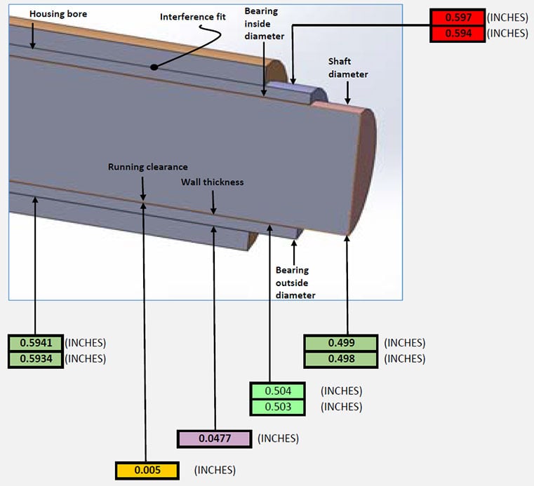
Bearing Selection and Achieving the Right Press Fit

Bushing Press Fit Tolerance Chart My XXX Hot Girl
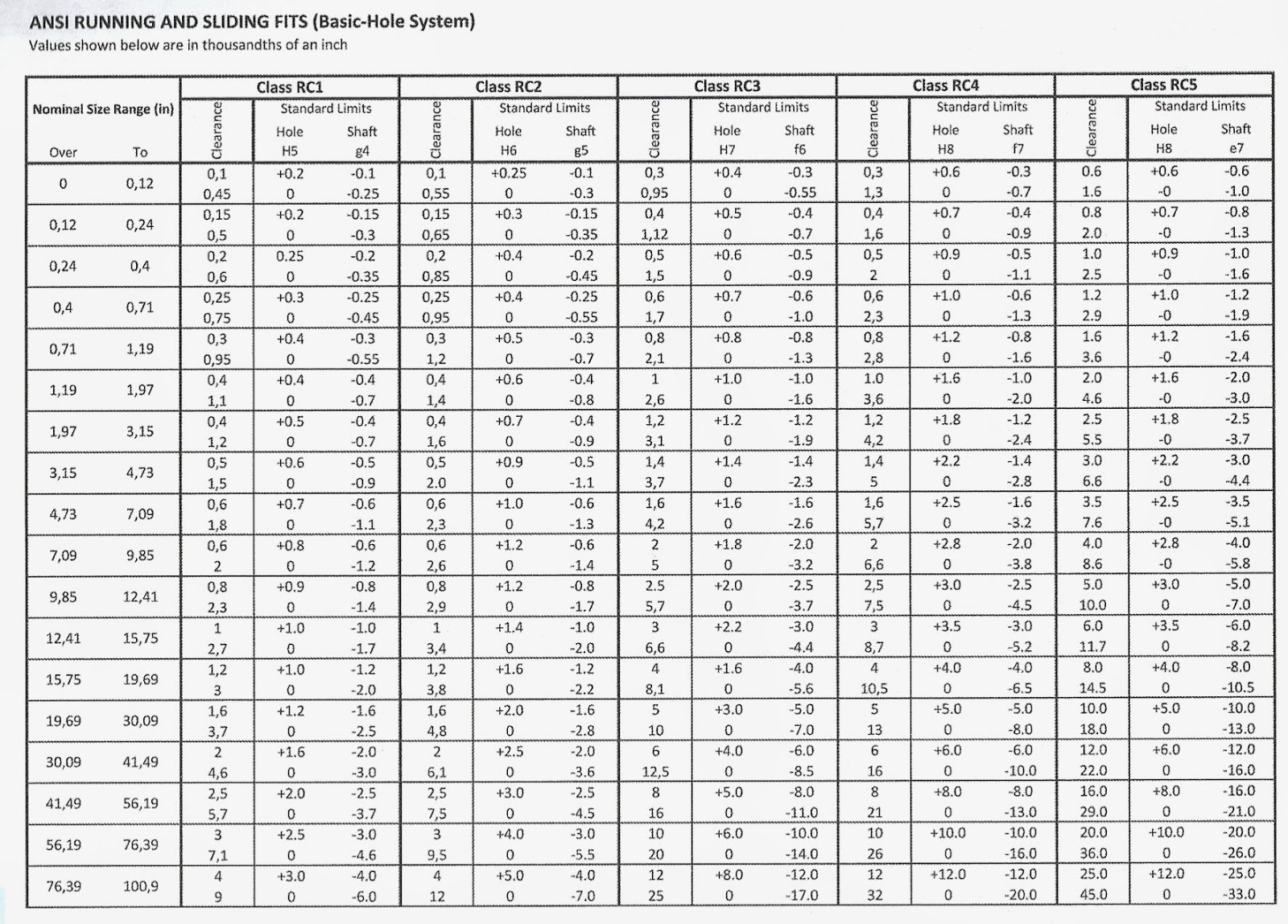
Press Fit Bearing Tolerance Chart

hole sizes for pressfit bushings in unhardened steel or

Press Fit Interference Chart
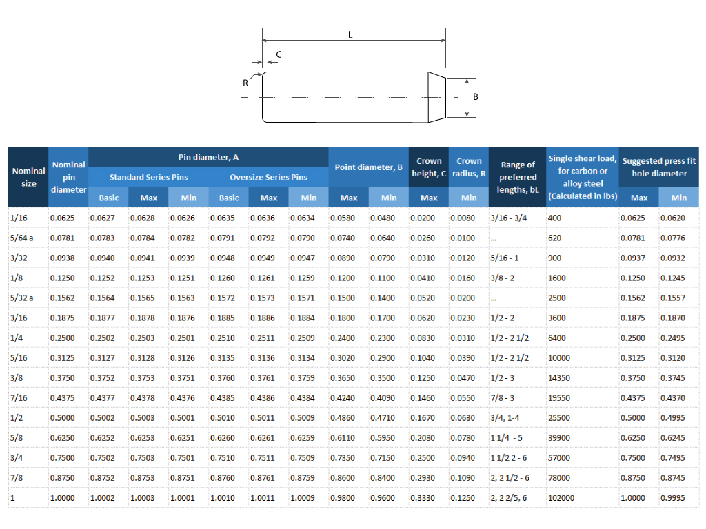
Too Tight or Perfect Fit? When to Use Press Fits in Your Assemblies
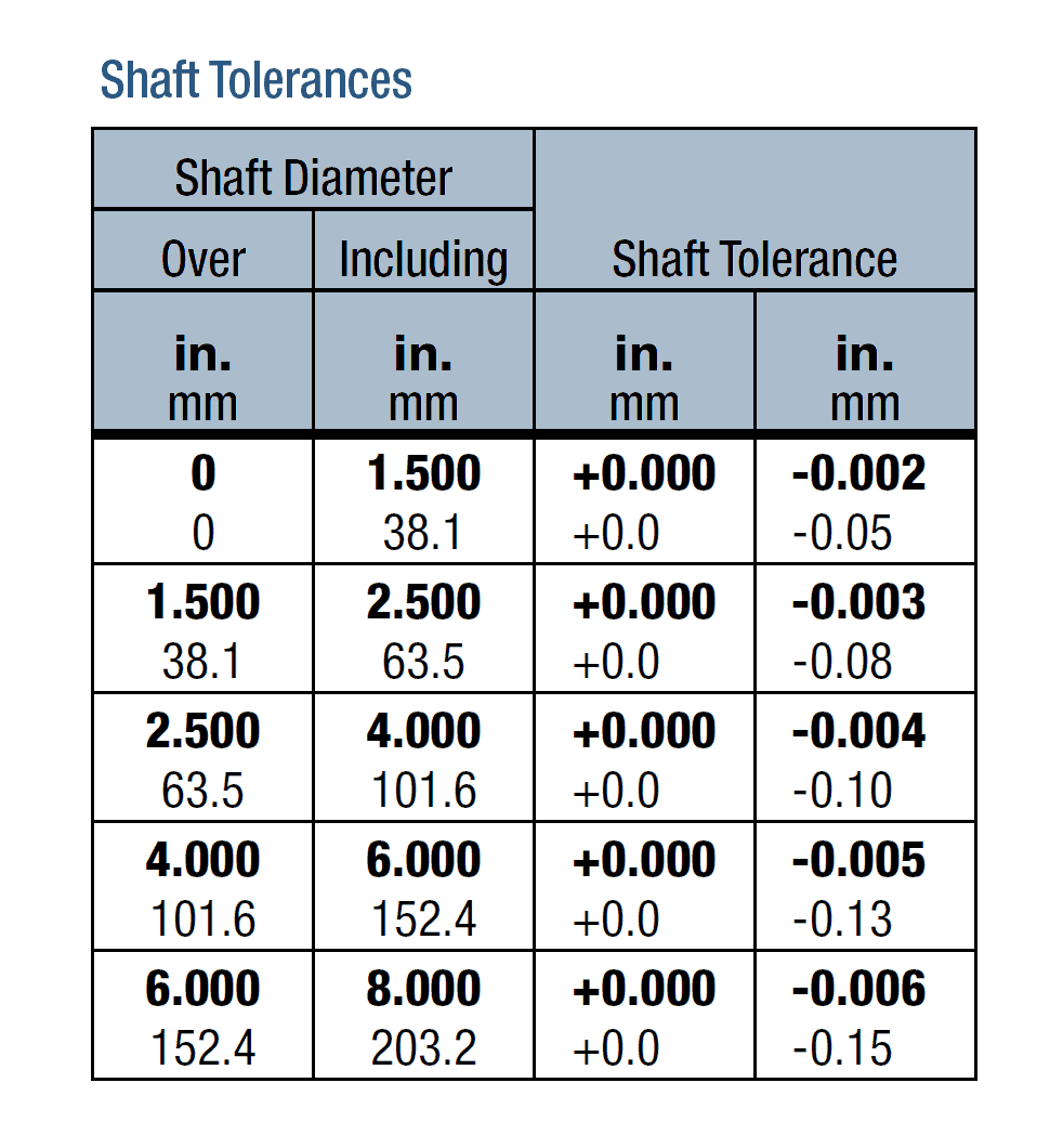
How to Install and Remove a Bushing Baart Industrial Group
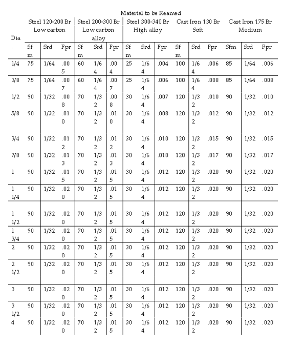
Bushing Press Fit Tolerance Chart Best Picture Of Chart

Press Fit Bushing Tolerance Chart

Press Fit Bushing Tolerance Chart
Web Learn About Tolerance In Press Fit, The Permissible Deviation From The Assigned Dimensions Of Mating Parts.
Find Your Data Faster With Our Fits Calculator.
Go Here, For Explanasions About The Terms Hole,.
Preferred Tolerances And Fits Charts (Ansi) Precision Measuring Tools For Shaft And Hole Measurements;
Related Post: