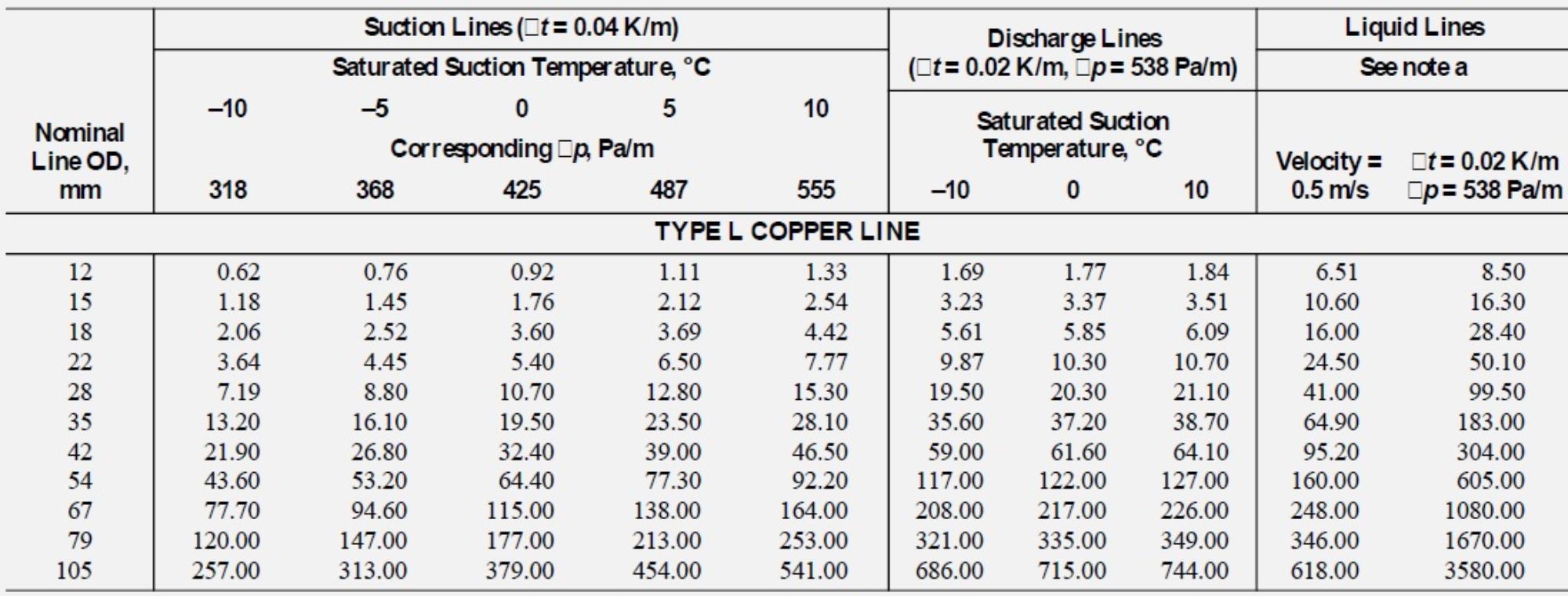
R410A Refrigerant Line Sizing Chart
R410A Refrigerant Line Sizing Chart - Suction line pressure loss due to friction. Air conditioning equipment and heat pumps. Residential piping and long line guideline. Staying within these guidelines and charging to a minimum of 10f (5.6 c) sub−cooling ensures a column of liquid is present at the txv. Use rated line sizes listed in unit specifications or installation instructions. Web practical refrigerant line sizes that limit pressure drop • avoid trapping excessive oil so that the compressor has enough oil to operate properly at all times These tables are based on extensive experimental measurements. • equivalent length is actual length plus friction losses caused by fittings and accessories. Web r410a refrigerant piping guide • refer to dupont refrigerant expert, version 2.0 for actual velocities and pressure drops. • minimize the number of 90º turns. • all selections are based on a maximum of 65 °f return gas entering the compressor and a refrigerant condensing and liquid line temperature of. Web the liquid line sizing charts in this guideline have been developed based on a txv metering device on the indoor coil. Web • where the refrigerant lines run through a wall or sill, they. These tables are based on extensive experimental measurements. • isolate the lines from all ductwork. Web • line sizes are expressed in outside diameter of type “l” copper tubing and calculated at rated full load system capacity. Examples showing how to perform an analysis appear in shaded outlined boxes. Web table 3, table 4, table 5, and table 6 in. Available in the following sizes. • isolate the lines from all ductwork. How to determine equivalent length. Figure 5 illustrates an example of a (4) tta/twa blower coil split system component arrangement. The third concern is refrigerant metering. Only qualified personnel should install and service the equipment. It does not apply to industrial refrigeration and/or variable refrigerant volume (vrv) systems. Available in the following sizes. • equivalent length is actual length plus friction losses caused by fittings and accessories. Web • line sizes are expressed in outside diameter of type “l” copper tubing and calculated at rated full. Suction line pressure loss due to friction. Use it to determine the proper, relative sequence of the components in the refrigerant lines that connect the (4) tta/twa outdoor unit to the blower coil. It does not apply to industrial refrigeration and/or variable refrigerant volume (vrv) systems. Web line sizes are expressed in outside diameter of type “l” copper tubing. Examples. The third concern is refrigerant metering. Figure 5 illustrates an example of a (4) tta/twa blower coil split system component arrangement. • minimize the number of 90º turns. • all selections are based on a maximum of 65 °f return gas entering the compressor and a refrigerant condensing and liquid line temperature of. Only qualified personnel should install and service. Only qualified personnel should install and service the equipment. Web the pressure loss due to vertical lift (evaporator above the condenser) depends on the difference in level between the metering device and condenser (or receiver) and on the density of the refrigerant. Tube size and component selection. Use rated line sizes listed in unit specifications or installation instructions. How to. Follow all suction line sizing recommendations to ensure system performance and adequate oil return for compressor lubrication. • equivalent length is actual length plus friction losses caused by fittings and accessories. All selections are based on a maximum of 65°f return gas entering the compressor and refrigerant condensing and. Web these line sizing charts are based on a suction pressure. Elevation changes affect pressure drop in refrigerant lines. How to determine equivalent length. Air conditioning equipment and heat pumps. Residential piping and long line guideline. • line sizes are expressed in outside diameter of type “l” copper tubing. Web practical refrigerant line sizes that limit pressure drop • avoid trapping excessive oil so that the compressor has enough oil to operate properly at all times The third concern is refrigerant metering. Web piping guide for suva® 410a (eng) • equivalent length is actual length plus friction losses caused by fittings and accessories. • all selections are based on. Web table 3, table 4, table 5, and table 6 in this guideline can be used to properly size suction lines. All selections are based on a maximum of 65°f return gas entering the compressor and refrigerant condensing and. Elevation changes affect pressure drop in refrigerant lines. Illustrations and figures are not to scale. If 51 to 80 linear feet: Examples showing how to perform an analysis appear in shaded outlined boxes. Line sizes are calculated at rated full load system capacity. These tables are based on extensive experimental measurements. Web • where the refrigerant lines run through a wall or sill, they should be insulated and isolated. Web the liquid line sizing charts in this guideline have been developed based on a txv metering device on the indoor coil. Follow all suction line sizing recommendations to ensure system performance and adequate oil return for compressor lubrication. Web liquid line sizes can be increased (or decreased) to minimize pressure loss (or gain) and improve oil return to the compressor. Suction line pressure loss due to friction. Web up to 50 linear feet: Web new tables of the thermodynamic properties of freontm 410a refrigerant (ashrae designation: • isolate the lines from all ductwork.
R410a Refrigerant Line Sizing Chart

410a Line Set Sizing Chart

R410a Refrigerant Line Sizing Chart

Refrigerant Pipe Size Chart R410a Labb by AG

Refrigerant line sizing Part I general principles and liquid lines
8 R410A Refrigerant Pipe Sizing Charts 2k23

8 R410A Refrigerant Pipe Sizing Charts 2k23

410A Pipe Sizing Chart

R410a Refrigerant Line Sizing Chart

8 R410A Refrigerant Pipe Sizing Charts 2k23
Residential Piping And Long Line Guideline.
The Third Concern Is Refrigerant Metering.
• All Selections Are Based On A Maximum Of 65 °F Return Gas Entering The Compressor And A Refrigerant Condensing And Liquid Line Temperature Of.
Air Conditioning Equipment And Heat Pumps.
Related Post:
