Rules For Dimensioning In Engineering Drawing
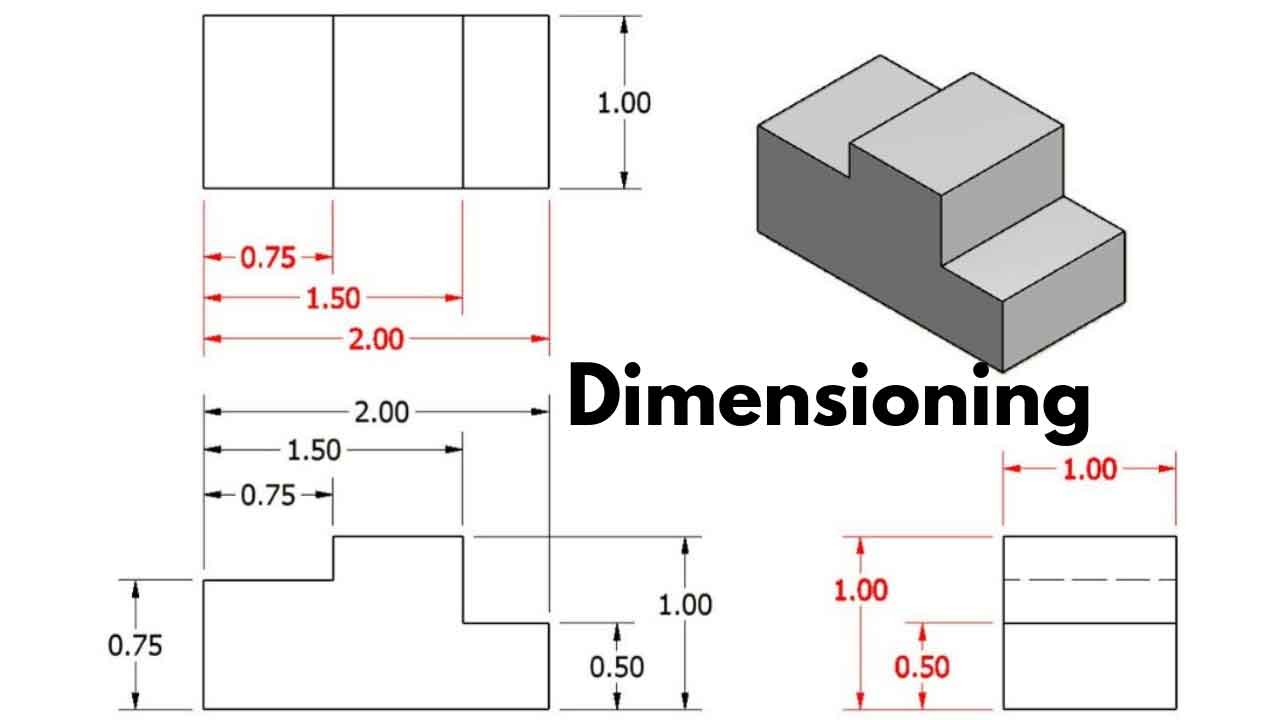
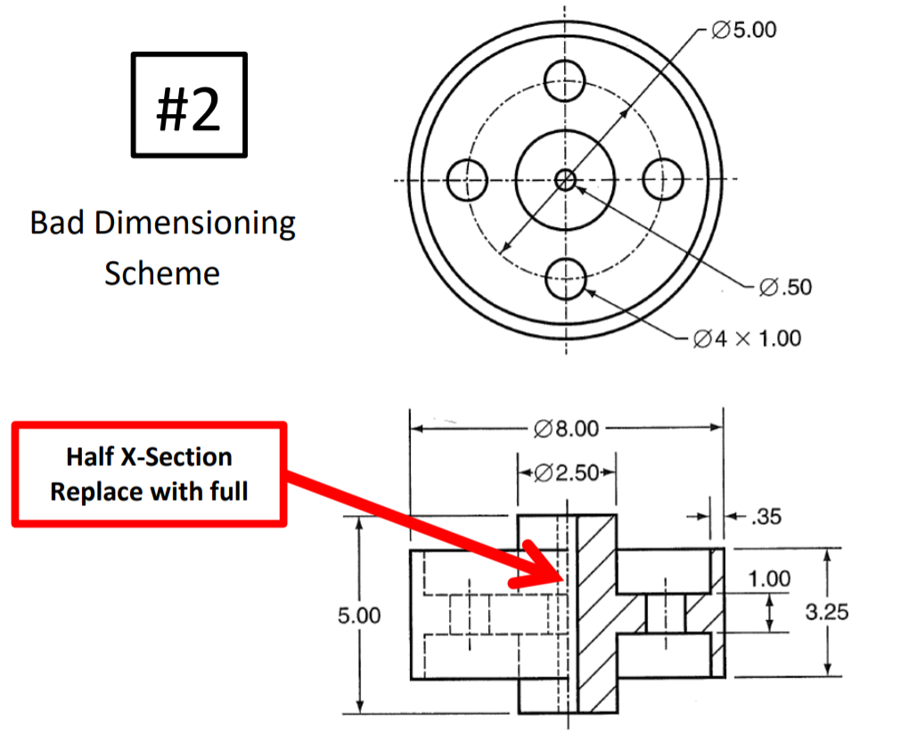
Rules For Dimensioning In Engineering Drawing - Web on a drawing used in american industry, all dimensions are in inches, unless otherwise stated. Here are seven general rules to follow when dimensioning. The exact shape of the part or assembly is shown by the different views in the drawing sheet. Web dimensioning rules in engineering drawing. Correct values must be given. Be sure that it is clear how dimensions are called out. It includes projection line, leader line, termination of the dimension line, the origin indication, symbols and the dimension itself. Most countries outside of the united states use the metric system of measure, or the international system of units (si), which is based on the meter. Dimensions less than six feet (72 in.) are given in inches. The fourteen fundamental rules are summarized below. Before an object can be built, complete information about both the size and shape of the object must be available. Be sure that it is clear how dimensions are called out. Each necessary dimension of an end product should be shown. Web here is how dimension lines should be sketched: Web size dimension the dimensions can be classified by types. The engineering drawings prepared by. Web avoid dimension with reference to the hidden lines of the drawing view and place it with respect to center lines. The dimensions in the part drawing shall be marked in accordance with the standard, complete, clear and reasonable. Each necessary dimension of an end product shall be shown or defined by model data. Web. Dimensions over six feet are usually shown in feet and inches. The fourteen fundamental rules are summarized below. The appropriate line quality must be used for legibility. Dimensions less than six feet (72 in.) are given in inches. Web dimension locations boundary dimensions and all text are always horizontal yes no grouping of dimensions grouped dimension diameter features diameter features. Here the width is the only horizontal size dimension. Dimensions less than six feet (72 in.) are given in inches. Web here is how dimension lines should be sketched: Web learn the fundamental rules of dimensioning in engineering/architectural/structural drawings.this youtube channel is dedicated to teaching people how to impr. It includes projection line, leader line, termination of the dimension line,. The fourteen fundamental rules are summarized below. Here the width is the only horizontal size dimension. Best practice 6 the largest dimension value should be placed furthest from the object so that smaller dimensions can be placed relatively closer to the object making the overall dimensioning clear. Each dimension has a tolerance. The appropriate line quality must be used for. The fourteen fundamental rules are summarized below. Methods and steps for dimensioning parts. Be sure that it is clear how dimensions are called out. The use of reference dimensions on a drawing should be minimized. Spacing and readability rule 1) dimensions should be arranged for maximum readability. No more dimensions than those necessary for complete definition shall be given. Dimensions should be given between points or surfaces that have a functional The fourteen fundamental rules are summarized below. Here are seven general rules to follow when dimensioning. Dimensions over six feet are usually shown in feet and inches. Each necessary dimension of an end product should be shown. Methods and steps for dimensioning parts. Year engineering students (btech and diploma students). Each dimension has a tolerance. The engineering drawings prepared by. The engineering drawings prepared by. Each necessary dimension of an end product shall be shown or defined by model data. The dimensions in the part drawing shall be marked in accordance with the standard, complete, clear and reasonable. Each dimension should be given clearly so it can be interpreted in only one way. Dimensions should not be duplicated or the. Web this video tutorial will be very helpful to our 1st. Dimensions should be shown in true profile views and refer to visible outlines on the part. It is indicated by arrowheads, it is drawn parallel to the surface whose length must be indicated. Basic requirements for dimensioning in part drawings. Dimensions must not be subject to more than one. Year engineering students (btech and diploma students). Web avoid dimension with reference to the hidden lines of the drawing view and place it with respect to center lines. Each dimension should be given clearly so it can be interpreted in only one way. Web the fundamental rules control the clarity and engineering intent of the dimensions on an engineering drawing. Web on a drawing used in american industry, all dimensions are in inches, unless otherwise stated. Dimensions should be given between points or surfaces that have a functional Methods and steps for dimensioning parts. Each dimension has a tolerance. Best practice 6 the largest dimension value should be placed furthest from the object so that smaller dimensions can be placed relatively closer to the object making the overall dimensioning clear. Spacing and readability rule 1) dimensions should be arranged for maximum readability. Here are seven general rules to follow when dimensioning. The fourteen fundamental rules are summarized below. Each necessary dimension of an end product should be shown. Before an object can be built, complete information about both the size and shape of the object must be available. Be sure that it is clear how dimensions are called out. It is indicated by arrowheads, it is drawn parallel to the surface whose length must be indicated.
Dimensioning Rules in Engineering Drawings YouTube

Dimensioning rules in engineering drawing

Dimensioning How To Clearly Communicate The Sizes Shapes Locations And

GENERAL RULES OF DIMENSIONING in Engineering Drawing YouTube

TECHNICAL MODELS AND ARTS BASICS IN DIMENSIONING

Rules For Dimensioning Mechanical Drawings Rules, Mechanic, Autocad

Rules For Dimensioning Mechanical Drawings YouTube

Dimensioning rules in engineering drawing

Dimensioning and sectioning in engineering drawing. Engineering Drawing
![Dimensioning Its Types, System, Principles. [A Comprehensive Guide].](https://civilseek.com/wp-content/uploads/2018/10/elements-of-dimensioning.jpg)
Dimensioning Its Types, System, Principles. [A Comprehensive Guide].
This Presentation Covers The Following Topics Within The Viewpoint Of Engineering Drawing.
Dimensions Should Be Shown In True Profile Views And Refer To Visible Outlines On The Part.
The Angle Begins As The Midpoint Of The 3” Long Dimension.
Basic, Reference Maximum, Minimum, Or Stock Dimensions.
Related Post: