Smith Chart Impedance Matching
Smith Chart Impedance Matching - Web impedance matching using smith charts. See examples, methods, and simulation tips for. Web the normalized source impedance, rs, is point a, and the normalized load impedance, rl, is point c. Since inductors and capacitors can be very lossy. Web learn how to plot impedance and determine impedance matching using a smith chart, a graphical tool for rf engineers. Web impedance matching networks are a core part of an rf circuit. Web the smith chart the smith chart allows easy calculation of the transformation of a complex load impedance through an arbitrary length of transmission line. This lecture explains the matching using lumed elements as well as matching using transmission line. The matching network must be lossless, which means that the design must. Web since z1 = 1 + i*2.228, we can exactly match this impedance to the center of the smith chart uses a series capacitor. Web this free online interactive smith chart tool is a calculator which can help you design matching networks and obtain maximum power transfer between your source and load. See examples, methods, and simulation tips for. Web a good amount of microwave design, such as designing a matching network for maximum power transfer, involves beginning with a load impedance plotted on. Web learn about impedance matching stub tuning using a smith chart, as well as single and double stub tuning, impedance contour, and the forbidden region of a. 50k views 3 years ago emp microwave. Web this free online interactive smith chart tool is a calculator which can help you design matching networks and obtain maximum power transfer between your source. Since inductors and capacitors can be very lossy. See examples, methods, and simulation tips for. Web the smith chart the smith chart allows easy calculation of the transformation of a complex load impedance through an arbitrary length of transmission line. This lecture explains the matching using lumed elements as well as matching using transmission line. Web learn about impedance matching. Web impedance matching basics: Web learn how to plot impedance and determine impedance matching using a smith chart, a graphical tool for rf engineers. See examples, methods, and simulation tips for. Web the normalized source impedance, rs, is point a, and the normalized load impedance, rl, is point c. The matching network must be lossless, which means that the design. By transforming the load impedance to a desired value, we can ensure that certain. The matching network must be lossless, which means that the design must. Web impedance matching basics: Web the smith chart the smith chart allows easy calculation of the transformation of a complex load impedance through an arbitrary length of transmission line. Web this free online interactive. Web a good amount of microwave design, such as designing a matching network for maximum power transfer, involves beginning with a load impedance plotted on a smith chart and. Web learn about impedance matching using a single stub, transmission lines, and immittance smith chart examples. Since inductors and capacitors can be very lossy. Web impedance matching networks are a core. Web impedance matching basics: The smith chart is one of the most important tools in understanding rf impedance and matching networks. The matching network must be lossless, which means that the design must. 50k views 3 years ago emp microwave. Web learn about impedance matching stub tuning using a smith chart, as well as single and double stub tuning, impedance. This lecture explains the matching using lumed elements as well as matching using transmission line. By transforming the load impedance to a desired value, we can ensure that certain. Web impedance matching basics: Web impedance matching using smith charts. Web learn about impedance matching stub tuning using a smith chart, as well as single and double stub tuning, impedance contour,. Web learn about impedance matching stub tuning using a smith chart, as well as single and double stub tuning, impedance contour, and the forbidden region of a. Web impedance matching basics: Web we can use the smith chart to perform inpedance matching. Web learn how to plot impedance and determine impedance matching using a smith chart, a graphical tool for. Web impedance matching basics: Web a good amount of microwave design, such as designing a matching network for maximum power transfer, involves beginning with a load impedance plotted on a smith chart and. Web the normalized source impedance, rs, is point a, and the normalized load impedance, rl, is point c. The smith chart is one of the most important. This lecture explains the matching using lumed elements as well as matching using transmission line. Web we can use the smith chart to perform inpedance matching. See examples, methods, and simulation tips for. Web the normalized source impedance, rs, is point a, and the normalized load impedance, rl, is point c. 304k views 4 years ago test & measurement fundamentals. 50k views 3 years ago emp microwave. Since inductors and capacitors can be very lossy. The matching network must be lossless, which means that the design must. Web impedance matching networks are a core part of an rf circuit. Web learn about impedance matching stub tuning using a smith chart, as well as single and double stub tuning, impedance contour, and the forbidden region of a. Web this free online interactive smith chart tool is a calculator which can help you design matching networks and obtain maximum power transfer between your source and load. Web a good amount of microwave design, such as designing a matching network for maximum power transfer, involves beginning with a load impedance plotted on a smith chart and. By transforming the load impedance to a desired value, we can ensure that certain. Web the smith chart the smith chart allows easy calculation of the transformation of a complex load impedance through an arbitrary length of transmission line. Web impedance matching using smith charts. Web learn about impedance matching using a single stub, transmission lines, and immittance smith chart examples.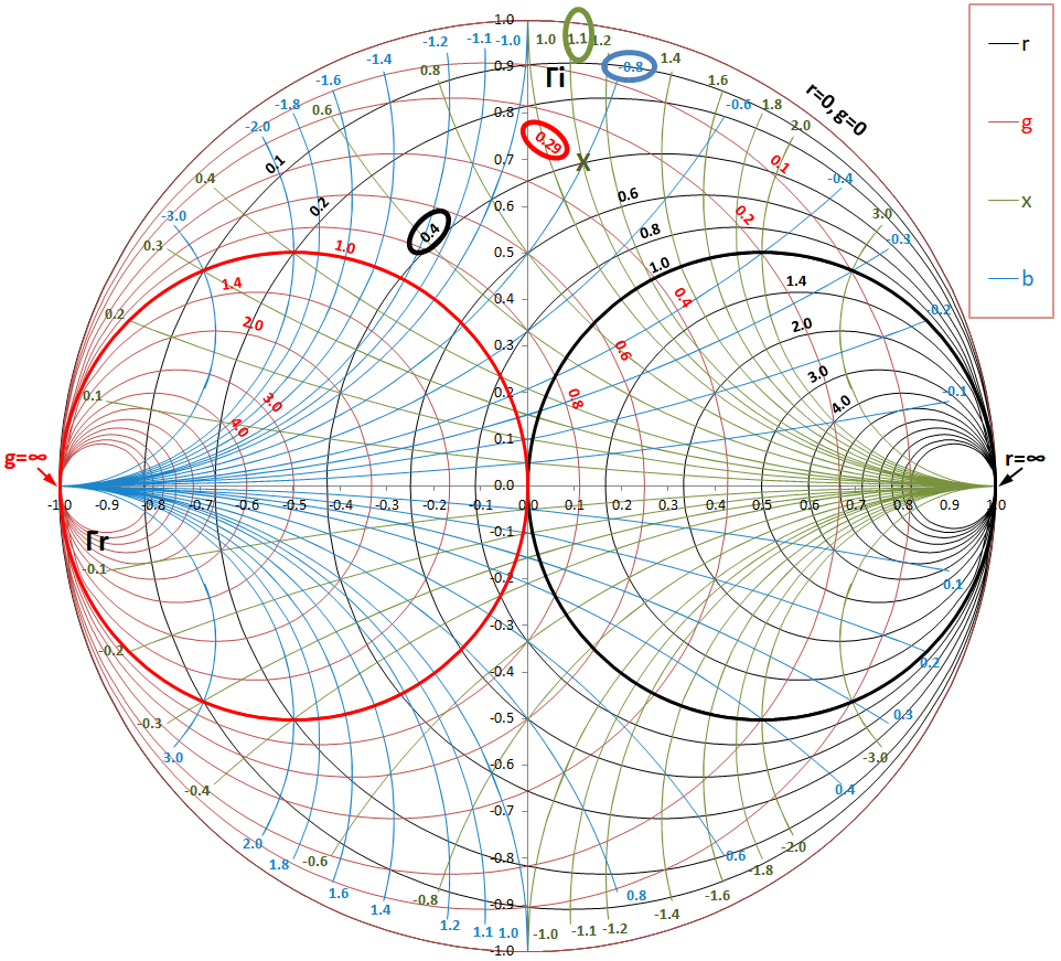
Impedance Matching by Using Smith Chart A StepbyStep Guide, Part II

Impedance Matching by Using Smith Chart A StepbyStep Guide, Part I

Impedance matching and the Smith chart, Part 2 Electrical Engineering

Design of impedance matching circuit using Smith chart (a) LC
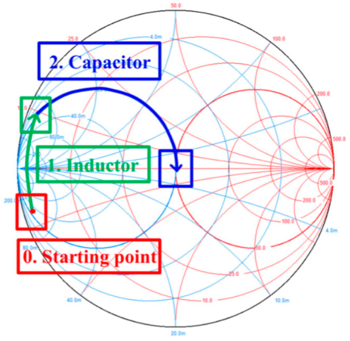
How To Read A Smith Chart yourlaxen

Exploring Single Stub Impedance Matching Through Smith Chart Examples
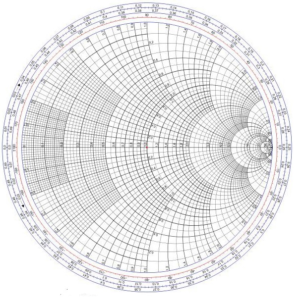
Impedance matching and the Smith Chart, Part 2 EE World Online A

Impedance Matching by Using Smith Chart A StepbyStep Guide, Part II
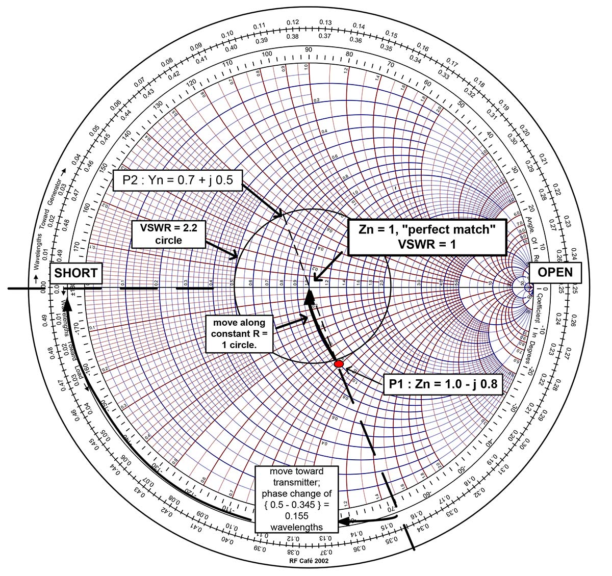
how to use a smith chart Jude Misaid
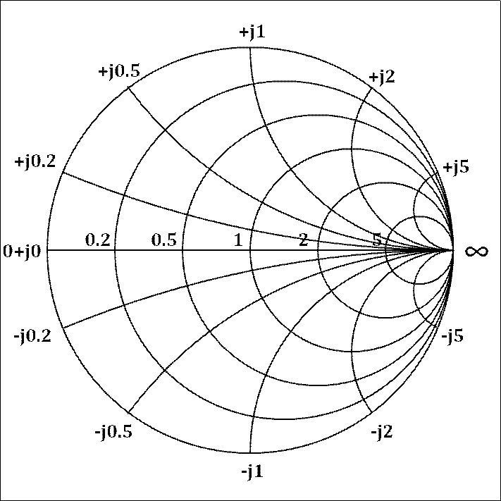
What is Smith Chart and how to use it for Impedance Matching
Web Impedance Matching Basics:
Web Learn How To Plot Impedance And Determine Impedance Matching Using A Smith Chart, A Graphical Tool For Rf Engineers.
Web Since Z1 = 1 + I*2.228, We Can Exactly Match This Impedance To The Center Of The Smith Chart Uses A Series Capacitor.
The Smith Chart Is One Of The Most Important Tools In Understanding Rf Impedance And Matching Networks.
Related Post: